
Designing an Appliance-Ready Wiring Diagram for a Shed
Running a simple extension cord to an outbuilding is a relic of the past. Modern sheds serve as workshops, home gyms, and secondary living spaces that demand serious power. When you are planning a wiring diagram for a shed, the primary focus must be on accommodating heavy appliance loads—such as deep freezers, mini-split air conditioners, space heaters, and 240V welders or EV chargers. Treating your shed like a detached appliance hub requires a dedicated subpanel fed by a 4-wire feeder circuit.
This comprehensive tutorial breaks down the exact electrical architecture, National Electrical Code (NEC) requirements, and material specifications needed to safely wire a shed subpanel in 2026. We will cover load calculations, trenching depths, grounding electrode systems, and the most common failure modes that cause breakers to trip or create dangerous shock hazards.
The Core Wiring Diagram Flow: Main Panel to Shed Appliances
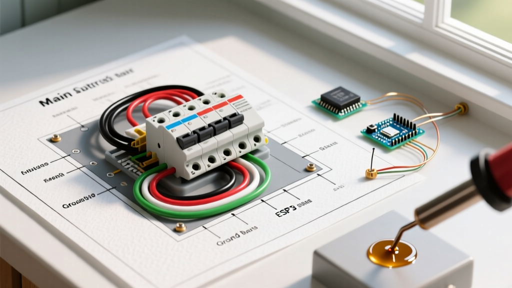
A compliant and safe shed wiring diagram follows a strict topology. You are essentially creating a micro-grid that isolates the shed's appliance loads from your main home's lighting and kitchen circuits. Here is the sequential flow of the diagram:
- Main Service Panel: A dedicated 60A or 100A 240V double-pole breaker is installed.
- The Feeder (4-Wire): Two hot wires (X and Y), one neutral (W), and one equipment grounding conductor (G) exit the main panel.
- Underground Conduit / Direct Burial: The feeder travels through Schedule 40 PVC or is buried as direct-feed UF-B / MHF cable.
- Shed Subpanel: The 4 wires terminate in a main-lug subpanel. Critical: The neutral and ground bus bars must be isolated (separated) in the subpanel.
- Branch Circuits: Individual single-pole (120V) and double-pole (240V) breakers feed specific appliances and receptacles.
- Grounding Electrode System: Two ground rods are driven into the earth outside the shed and bonded to the subpanel's ground bus.
Shed Appliance Load Matrix & Wire Gauge Sizing
To design your diagram accurately, you must calculate the continuous and non-continuous loads of the appliances you plan to run. The NEC requires continuous loads (running for 3 hours or more, like a freezer or heater) to be derated to 125% of their maximum draw.
| Appliance Type | Voltage | Max Amp Draw | Required Breaker | Branch Wire Gauge (Copper) |
|---|---|---|---|---|
| Deep Freezer (Dedicated) | 120V | 5A - 8A | 20A 1-Pole (GFCI) | 12 AWG |
| Mini-Split AC (e.g., Pioneer 12k BTU) | 208-230V | 12A | 20A 2-Pole | 12 AWG |
| 1500W Space Heater (Cadet F-Series) | 120V | 12.5A | 20A 1-Pole | 12 AWG |
| MIG Welder (120V input) | 120V | 20A | 30A 1-Pole | 10 AWG |
| Level 2 EV Charger (32A) | 240V | 32A | 50A 2-Pole | 6 AWG |
Note: Always consult the manufacturer's specification sheet for the exact Minimum Circuit Ampacity (MCA) and Maximum Overcurrent Protection (MOP) before finalizing your branch circuit wiring.
Feeder Sizing and Voltage Drop Calculations
The most frequent mistake in shed wiring diagrams is sizing the feeder wire strictly based on ampacity while ignoring voltage drop. If your shed is 150 feet from the main panel, a standard 6 AWG copper wire on a 60A breaker will experience significant voltage drop when a heavy appliance compressor kicks on, potentially damaging the appliance motor.
According to industry standards referenced by the Southwire Voltage Drop Calculator, you should aim for a maximum 3% voltage drop on branch circuits and a combined 5% drop on the feeder and branch. For a 100-foot run pulling 60A at 240V, upsizing your feeder to 2 AWG Aluminum (MHF cable) or 4 AWG Copper is highly recommended to maintain clean, stable voltage for sensitive appliance control boards.
Trenching and Physical Installation Specifications
When translating your wiring diagram into physical reality, burial depth is strictly governed by the NEC. Failure to meet these depths will result in a failed inspection and potential damage from future landscaping.
- Rigid Metal Conduit (RMC): 6 inches burial depth.
- PVC Conduit (Schedule 40/80) with THHN wires: 18 inches burial depth. This is the preferred method for future-proofing, allowing you to pull thicker wires later if you add a larger welder or hot tub.
- Direct Burial UF-B or MHF Cable: 24 inches burial depth. While cheaper upfront and requiring no conduit, direct burial is highly susceptible to damage from shovel strikes and rodent chewing.
Always install a warning ribbon 12 inches above the buried conduit or cable to alert anyone digging in the future.
The Subpanel and Grounding Electrode System
The shed subpanel is the heart of your appliance wiring diagram. Modern code mandates a 4-wire feeder. The obsolete 3-wire feed (where the neutral and ground were bonded at the subpanel) is incredibly dangerous because it allows normal neutral return current to flow through the earth and the shed's metal framing, creating a severe shock hazard.
NEC Code Alert: According to the NFPA National Electrical Code (Article 250.32), a separate equipment grounding conductor must be run with the circuit conductors to any outbuilding. The neutral bus bar in the shed subpanel must be completely isolated from the metal enclosure and the ground bus bar.
Furthermore, the shed requires its own Grounding Electrode System. You must drive two copper-clad steel ground rods (minimum 8 feet long, 5/8 inch diameter) into the earth, spaced at least 6 feet apart. These rods are bonded to the subpanel's ground bus using a bare 6 AWG or 8 AWG copper wire. This system protects against lightning strikes and static buildup, but it does not replace the equipment grounding conductor running back to the main house.
Material Cost Breakdown (2026 Estimates)
Budgeting for a 100A shed subpanel installation requires accounting for copper and aluminum market fluctuations. Here is a realistic material cost breakdown for a 100-foot run using 2-2-2-4 Aluminum MHF (Mobile Home Feeder) cable, which is the most cost-effective choice for DIYers and pros alike in 2026.
- 100A Main Lug Subpanel (e.g., Siemens P2S4012): $75
- 60A Double-Pole Breaker (Main Panel Feed): $45
- 200 ft of 2-2-2-4 Aluminum MHF Cable: $190
- Schedule 40 PVC Conduit & Fittings (100 ft): $120
- Branch Breakers (Assorted AFCI/GFCI): $150
- Ground Rods, Clamps, and Bare Copper Wire: $45
- Total Estimated Material Cost: $625
Note: This excludes the cost of trenching equipment rental and permit fees, which vary wildly by municipality.
Common Failure Modes and Troubleshooting
Even with a perfect wiring diagram, execution errors can lead to appliance failure or safety hazards. Watch out for these specific failure modes:
1. Shared Neutral on Multi-Wire Branch Circuits (MWBC)
If you use an MWBC to save wire on 120V appliance circuits, both hot legs must be on a handle-tied double-pole breaker. If they are on separate single-pole breakers and both are turned on to the same phase, the shared neutral will carry the sum of the currents rather than the difference, melting the wire and causing a fire.
2. Missing AFCI/GFCI Protection
As detailed by Electrical Contractor Magazine Codes & Standards, recent NEC updates require GFCI protection on all 125V, 15A, and 20A receptacles in outbuildings. Furthermore, if the shed contains living quarters or specific appliance zones, AFCI (Arc Fault) protection may be required on the branch breakers. Standard breakers will fail inspection.
3. Loose Neutral Connections Causing Overvoltage
If the main feeder neutral wire is loose at the subpanel, the 240V split-phase system becomes unbalanced. When a heavy 120V appliance like a space heater turns on, the voltage on that leg will drop to 90V, while the voltage on the opposite leg will spike to 150V. This 150V surge will instantly destroy the control boards of sensitive appliances like mini-split ACs or smart freezers. Always torque subpanel lugs to the manufacturer's specified inch-pound rating using a calibrated torque screwdriver.
Final Inspection and Energization
Before flipping the main feeder breaker, double-check your wiring diagram against the physical installation. Verify that the ground and neutral bars are isolated, the grounding rods are properly clamped, and all wire strippings are clean with no exposed copper outside the breaker terminals. Once your local electrical inspector signs off on the rough-in and final trenching, you can safely energize the subpanel and begin plugging in your heavy-duty shed appliances with total confidence.