
Decoding the Wiring Diagram for a Heat Pump Motor Circuit
Heat pumps represent one of the most complex residential motor circuits in modern HVAC systems. Unlike standard air conditioners, a heat pump must seamlessly reverse refrigerant flow while managing variable-speed compressor motors, dual run capacitors, and intricate defrost control boards. When interpreting a wiring diagram for a heat pump, technicians and advanced DIYers must distinctly separate the 240V high-voltage power circuit from the 24V low-voltage control logic. According to the U.S. Department of Energy, the rapid adoption of cold-climate heat pumps has introduced advanced inverter topologies that fundamentally change how compressor motors are wired and diagnosed in 2026.
CRITICAL SAFETY WARNING: Heat pump outdoor units contain lethal 240V line voltage and high-voltage DC bus capacitors in inverter models. Always perform Lockout/Tagout (LOTO) at the main service panel and the outdoor disconnect switch. Verify zero energy with a CAT III or CAT IV multimeter, and use a 20k-ohm bleeder resistor to discharge run capacitors before touching any motor terminals.
Core Components in Standard PSC Heat Pumps
For traditional Permanent Split Capacitor (PSC) compressors and fan motors, the wiring diagram revolves around a few critical nodes. Understanding these components is mandatory before tracing the schematic:
- Contactor (e.g., Mars 21010 30A): The heavy-duty relay that bridges 240V line power to the compressor and fan motors when the 24V coil is energized by the thermostat or defrost board.
- Dual Run Capacitor (e.g., Gentek 45/5 MFD 440VAC): Provides the necessary phase shift for the start winding of the compressor (45 MFD) and the fan motor (5 MFD).
- Compressor Motor Terminals: Labeled C (Common), R (Run), and S (Start). The internal windings dictate the electrical path.
- Defrost Control Board: Monitors coil temperature and initiates the reversing valve solenoid to melt ice off the outdoor coil during winter operation.
Step-by-Step: Tracing the High-Voltage Compressor Path
To effectively read the schematic, follow the current path from the disconnect to the compressor hermetic terminals. This sequence applies to standard 3-ton to 5-ton residential units (e.g., Carrier Performance or Trane XR series):
- Line Voltage Entry: L1 and L2 (240V) enter the outdoor unit from the 60A non-fused or 30A fused disconnect box via 10 AWG or 8 AWG THHN/THWN copper wire.
- Contactor Lugs: L1 and L2 land on the top line-side lugs of the contactor. The bottom load-side lugs feed the compressor and fan motor circuits.
- Common (C) Path: A direct wire (often black or uninsulated) runs from the L2 load-side lug directly to the 'C' terminal on the compressor. This bypasses the contactor's switching mechanism for one leg, meaning the compressor casing can remain energized even if the contactor is open. Never assume a compressor is dead just because the contactor is disengaged.
- Run (R) Path: A wire runs from the L1 load-side lug, through the contactor switch, to the 'R' terminal on the compressor.
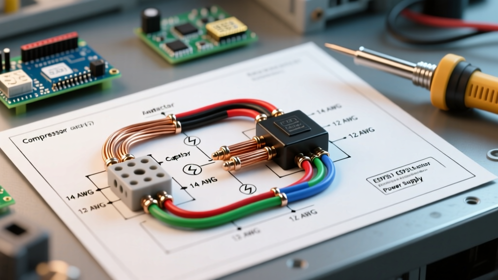
- Start (S) & Capacitor Path: The 'S' terminal wires directly to the 'HERM' (Hermetic) terminal on the dual run capacitor. The 'C' terminal on the capacitor wires back to the L2 line voltage. This creates the phase-shifted magnetic field required to spin the motor rotor.
Compressor Motor Troubleshooting Matrix
When a heat pump trips the breaker or fails to start, the wiring diagram guides your multimeter testing. Disconnect all wires from the compressor terminals and measure resistance (Ohms) across the pins. Use the formula: R-S = R-C + C-S.
| Measurement Points | Expected Reading (3-Ton Scroll) | Failure Mode Indicated | Corrective Action |
|---|---|---|---|
| C to R (Run Winding) | 1.5 - 3.0 Ohms | Open Circuit (OL) | Internal overload tripped or broken winding. Cool unit and retest; replace if OL persists. |
| C to S (Start Winding) | 3.0 - 6.0 Ohms | Short Circuit (Near 0 Ohms) | Winding insulation failure. Compressor must be replaced. |
| R to S (Total Winding) | 4.5 - 9.0 Ohms | Reading does not equal C-R + C-S | Shorted turns between windings. Replace compressor. |
| Any Pin to Copper Ground | OL (Infinite) | Any reading below 500k Ohms | Ground fault (burned varnish). Compressor is destroyed; check acid in refrigerant lines. |
The Reversing Valve Solenoid: Heat Pump Specifics
What truly separates a heat pump wiring diagram from a standard AC schematic is the reversing valve solenoid. This 24V coil physically shifts the pilot valve, redirecting high-pressure discharge gas to either heat or cool the indoor space. In most modern brands (like Rheem and Ruud), the solenoid is energized in Cooling mode (O terminal). In brands like Trane and Lennox, it is energized in Heating mode (B terminal). If the wiring diagram shows the 'O' terminal connected to the defrost board, but the thermostat is configured for 'B', the system will provide heat when calling for AC, and vice versa. Always verify the energized state against the manufacturer's schematic during commissioning.
2026 Perspective: Inverter-Driven Cold-Climate Heat Pumps
The landscape of HVAC motor wiring has shifted dramatically. As noted by ENERGY STAR certification requirements for 2026, ultra-efficient cold-climate heat pumps (such as the Mitsubishi Hyper-Heat MXZ series or Bosch IDS 3.0) utilize variable-speed inverter compressors. The wiring diagrams for these units discard the traditional contactor and run capacitor entirely.
Instead, line voltage (240V AC) feeds directly into an Inverter PCB. The board utilizes a bridge rectifier to convert AC to high-voltage DC (often 350V-400V DC on the bus capacitors), then uses Insulated Gate Bipolar Transistors (IGBTs) to chop the DC into a simulated 3-phase AC waveform. Consequently, the compressor motor wiring features three identical terminals labeled U, V, and W. There is no Common, Run, or Start winding. Troubleshooting these motors requires checking the phase-to-phase resistance (U-V, V-W, U-W), which should be perfectly balanced (typically between 1.0 and 3.0 Ohms depending on the model). If the inverter board outputs an error code for 'DC Bus Undervoltage' or 'Compressor Lock', the wiring diagram directs you to test the IPM (Intelligent Power Module) on the board rather than swapping a capacitor.
NEC Wire Sizing & Overcurrent Protection
Proper wire sizing is dictated by the unit's nameplate, specifically the Minimum Circuit Ampacity (MCA) and Maximum Overcurrent Protection (MOCP). According to Article 440 of the National Fire Protection Association (NFPA 70 / NEC), HVAC motor circuits have unique sizing rules that differ from standard branch circuits. The breaker size (MOCP) is intentionally oversized to handle the Locked Rotor Amps (LRA) during compressor startup without nuisance tripping, while the wire gauge is sized strictly to the MCA.
| Nameplate MCA | Nameplate MOCP | Required Copper Wire (THHN/THWN) | Breaker Type |
|---|---|---|---|
| 14.0 Amps | 25 Amps | 14 AWG (NEC 240.4(G) exception) | 25A HACR Type |
| 18.5 Amps | 30 Amps | 12 AWG | 30A HACR Type |
| 24.0 Amps | 40 Amps | 10 AWG | 40A HACR Type |
| 32.0 Amps | 50 Amps | 8 AWG | 50A HACR Type |
Note: Always use HACR (Heating, Air Conditioning, and Refrigeration) rated breakers, which are specifically designed to handle the magnetic inrush currents of motor loads without tripping prematurely. When routing low-voltage 18 AWG or 14 AWG control wires alongside high-voltage lines, maintain a minimum 2-inch separation or use physical barriers to prevent electromagnetic interference (EMI) from inducing phantom voltages in the thermostat communication lines.
Mastering the schematic is the difference between blindly swapping parts and executing precision diagnostics. Whether you are tracing a 24V defrost signal on a legacy PSC unit or analyzing a 3-phase inverter output on a 2026 cold-climate system, the wiring diagram remains your ultimate roadmap to safe and efficient motor operation.