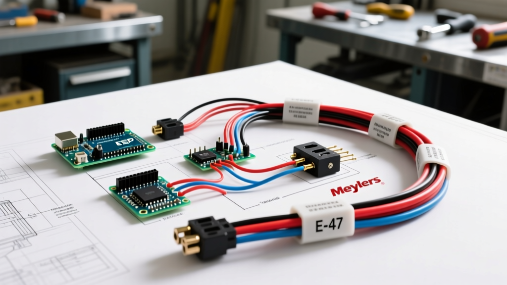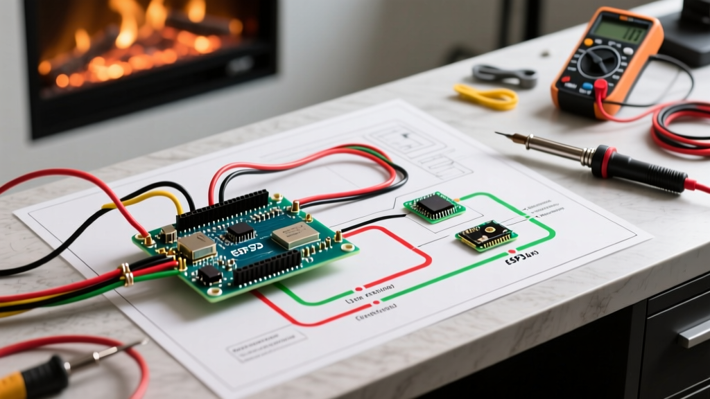

Understanding the RV Thermostat Wiring Paradigm
When homeowners attempt to apply residential HVAC knowledge to recreational vehicles, they immediately run into a critical roadblock: voltage. Residential thermostats operate on 24V AC control circuits, whereas the standard wiring diagram for RV thermostat systems relies entirely on 12V DC power from the coach battery bank. As of 2026, while high-end motorhomes are adopting 120V AC residential units, the vast majority of travel trailers and fifth wheels still utilize 12V DC control logic.
In an RV, the wall-mounted thermostat does not send a low-voltage signal to a transformer. Instead, it acts as a series of mechanical or solid-state switches that route raw 12V DC power directly to the relays located on the air conditioner's main control board. Misunderstanding this fundamental difference is the leading cause of blown control board fuses and fried compressor contactors during DIY thermostat replacements.
Critical Safety Warning
Never connect a standard 24V AC residential thermostat (like a Nest or Ecobee) to an RV's 12V DC wiring harness. Doing so will instantly destroy the thermostat's internal relays and can cause a catastrophic short circuit, violating safety standards outlined in NFPA 1192 (Standard on Recreational Vehicles).
The Standard 4-Wire Coleman Mach Wiring Diagram
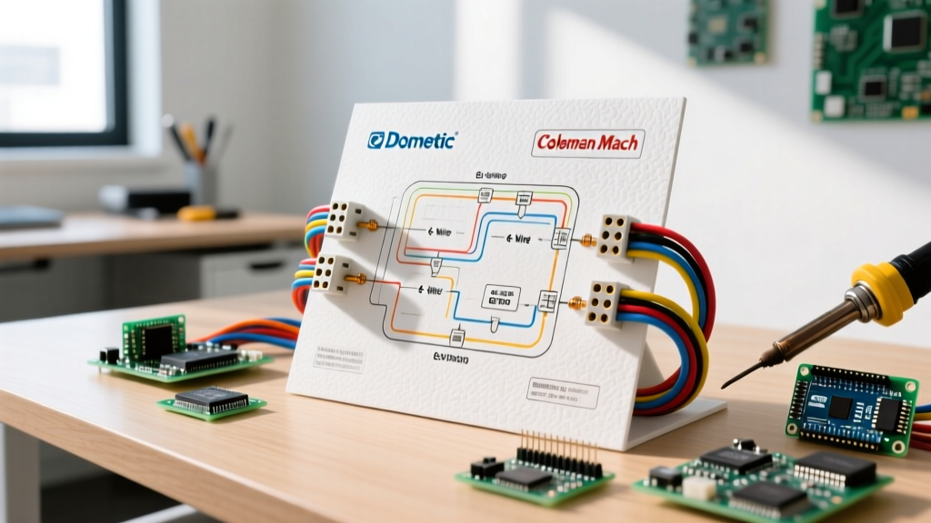
The 4-wire configuration is the most ubiquitous analog setup in the RV industry, heavily utilized by Coleman Mach (such as the classic 8330-3851 series) and older Dometic Duo-Therm units. This setup controls basic cooling, heating, and fan operations.
4-Wire Pinout and Color Code Matrix
| Wire Color | Terminal Label | Function | Control Board Relay |
|---|---|---|---|
| Red | RH / 12V+ | Main 12V DC Power In | Feeds all internal switches |
| White | FAN | Blower Motor High Speed | Fan Relay (12V+ Out) |
| Yellow | COOL | Compressor Clutch | Cooling Relay (12V+ Out) |
| Green/Blue | HEAT | Furnace or Heat Pump | Heat Relay (12V+ Out) |
Note: In Coleman Mach units, the Red wire provides the 12V+ source. When you turn the dial to 'Cool', the internal switch connects the Red wire to the Yellow wire, sending 12V+ up to the roof unit's control board to energize the compressor contactor.
The 6-Wire Dometic Analog Wiring Diagram
For RVs equipped with dual-pane windows, larger floorplans, or heat pump configurations, a 6-wire harness is often required. This adds automation logic and auxiliary electric heating elements.
- Red (12V+): Main power feed.
- White (Fan): Blower motor control.
- Yellow (Cool): Compressor engagement.
- Blue (Heat Pump): Reversing valve and compressor for heat pump mode.
- Green (Furnace): 12V propane furnace blower and gas valve trigger.
- Black/Brown (Auto/Aux): Engages the 120V AC electric resistance heating strip when ambient temperatures drop below the heat pump's efficiency threshold (usually 35°F).
Modern Upgrades: The Digital Data Bus Shift
If you are consulting a wiring diagram for RV thermostat upgrades in 2026, you will likely encounter digital data-bus systems. Modern units like the Dometic Comfort Control Center 2 (CCC2) or the Micro-Air EasyTouch Pro (retailing around $349) do not use individual wires for each function. Instead, they utilize a 4-pin RJ11 or RJ12 telephone-style cable.
In a data-bus system, the thermostat is essentially a computer terminal. Two wires carry 12V DC power, and two wires carry digital serial commands. The actual heavy-duty relays are housed entirely inside the roof-mounted control box. If your RV was built after 2018 with a factory-installed Dometic digital system, you cannot wire a standard 4-wire analog thermostat without installing a proprietary adapter board (such as the Micro-Air ADPT-01, approx. $85).
Analog vs. Digital Thermostat Comparison
| Feature | 4/6-Wire Analog | Digital Data-Bus (CCC2/EasyTouch) |
|---|---|---|
| Wiring Harness | Individual stranded copper wires | 4-pin RJ11/RJ12 shielded cable |
| Temperature Accuracy | +/- 3°F (Mechanical bimetal) | +/- 0.5°F (Digital thermistor) |
| Programmability | None (Manual dials/sliders) | Full scheduling & auto-changeover |
| Average Replacement Cost | $45 - $80 | $160 - $350 |
Wire Gauge Selection and Voltage Drop Mathematics
The most frequently overlooked aspect of RV thermostat wiring is wire gauge. Because 12V DC systems operate at high amperage relative to their voltage, voltage drop over distance is a severe issue. According to guidelines supported by the RV Industry Association (RVIA), undersized wiring leads to 'relay chatter'—a rapid clicking sound from the roof unit that will eventually weld the contactor contacts together, destroying the AC compressor.
Wire Sizing Guide for 12V Thermostat Runs
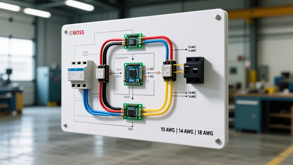
- Up to 15 feet: 18 AWG stranded copper is sufficient. Voltage drop will remain under 2%.
- 15 to 30 feet: Upgrade to 16 AWG stranded copper. This is critical for rear-bedroom AC units in long fifth wheels.
- Over 30 feet: Use 14 AWG stranded copper.
Pro Tip: Never use solid-core residential thermostat wire (18/5 or 18/8). The constant vibration of an RV in transit will cause solid-core copper to work-harden, snap, and create intermittent shorts behind the wall panel. Always use stranded, automotive-grade GXL or SXL wire.
Step-by-Step: Upgrading an Analog 4-Wire to Micro-Air EasyTouch
If you are retaining your original 4-wire harness but upgrading to a modern digital wall plate like the Micro-Air EasyTouch (which supports legacy analog wiring), follow this precise sequence to avoid blowing the roof unit's fuse.
- Isolate Power: Turn off the 120V AC breaker for the air conditioner at the main distribution panel AND disconnect the 12V DC coach battery negative terminal. The control board holds both voltages.
- Verify the Fuse: Locate the 3A or 5A ATO blade fuse on the AC control board in the roof unit. Ensure it is intact before starting. If it is already blown, your new thermostat will not power on, leading to false diagnostic conclusions.
- Map the Legacy Wires: Label the existing Red, White, Yellow, and Green wires. Do not trust the previous owner's color coding; use a multimeter to verify which wire has 12V+ continuity from the coach battery (the Red wire).
- Connect to the EasyTouch Baseplate: Insert the 18 AWG stranded wires into the spring-loaded terminal blocks on the Micro-Air baseplate. Ensure no stray copper strands are bridging adjacent terminals.
- Test the Relays: Reconnect the 12V battery. Set the thermostat to 'Fan Only'. Listen for a distinct, single 'click' from the roof unit. If you hear rapid clicking, immediately power down—your wire gauge is too small, or the 12V+ feed has a high-resistance corrosion point.
Troubleshooting Common Wiring Failures
1. The 'Dead' Thermostat (No Display)
If the digital display is blank, the 12V+ Red wire is not reaching the unit. Check the 12V DC fuse panel in the RV's main living area. Look for a 15A or 20A fuse labeled 'AC Control' or 'Furnace'. Additionally, inspect the inline 3A glass AGC fuse located directly on the Dometic/Coleman roof control board.
2. Compressor Runs, But Blower Fan Does Not
This indicates a break in the White (Fan) wire circuit, or a failed fan relay on the roof board. Using a multimeter, check for 12V DC at the White wire terminal on the thermostat baseplate when the fan is commanded 'ON'. If 12V is present at the wall but the fan doesn't run, the fault lies in the roof-mounted control board relay or the blower motor capacitor.
3. Heat Pump Blows Cold Air
In 6-wire setups, if the heat pump is engaged but the air is freezing, the Blue wire (reversing valve) is either not receiving 12V+ or the solenoid coil on the roof unit has failed. Furthermore, if the ambient temperature is below 35°F, the heat pump cannot extract thermal energy from the outside air; the system must automatically switch to the Aux/Electric strip heat via the Black/Brown wire circuit.
Expert Insight: When diagnosing RV HVAC control boards, always reference the specific manufacturer's schematic. Dometic and Coleman Mach use completely different logic gates for their delay timers. Coleman utilizes a 3-minute compressor delay timer built into the board, whereas older Dometic analog systems rely on the thermostat's internal bimetallic anticipation heater. Bypassing these delays by shorting wires will result in catastrophic compressor slugging. For official schematics and warranty support, always consult the Dometic Support Portal or Coleman Mach technical documentation.
Final Thoughts on RV Climate Control Wiring
Mastering the wiring diagram for RV thermostat systems requires respecting the 12V DC environment. By selecting the correct stranded wire gauge, understanding the relay-switching logic, and recognizing the transition toward digital data-bus architectures, you can confidently diagnose, repair, and upgrade your RV's climate control system. Whether you are maintaining a legacy 4-wire Coleman Mach or retrofitting a modern Micro-Air touchscreen, precision and adherence to NFPA 1192 low-voltage standards will ensure your system operates reliably for seasons to come.