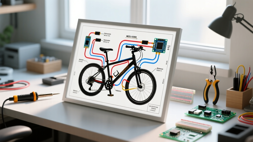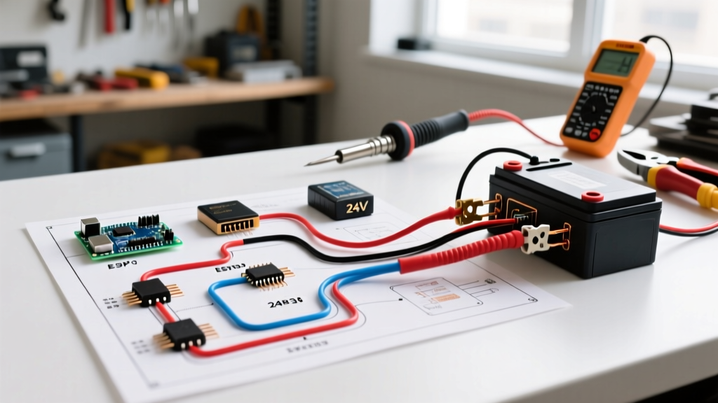

Introduction to 24V DC Scooter Architecture
Building, repairing, or upgrading a 24-volt electric scooter requires a precise understanding of low-voltage DC architecture. Whether you are retrofitting a classic Razor E300, wiring a generic 350W BLDC commuter, or designing a custom kids' mobility cart, a proper schematic 24 volt electric scooter wiring diagram is your most critical safety document. In 2026, the shift from heavy Sealed Lead Acid (SLA) batteries to lightweight 7S and 8S Lithium-ion and LiFePO4 packs has changed how we approach main power loops, making Battery Management System (BMS) integration just as important as the motor controller itself.
This comprehensive walkthrough breaks down the exact wiring sequence, wire gauge requirements, and edge-case troubleshooting needed to get your 24V system running safely and efficiently. According to the U.S. CPSC Micromobility Safety Guidelines, improper wiring and lack of overcurrent protection remain the leading causes of thermal runaway in DIY micro-mobility projects. Let's eliminate those risks.
Core Component Breakdown
Before cutting a single wire, verify your component specifications. A standard 24V system operates nominally at 24V, but fully charged SLA packs read 25.6V, while a 7S Li-ion pack reads 29.4V. Ensure your controller is rated for the peak voltage.
| Component | Specification / Model Example | Function |
|---|---|---|
| Battery Pack | 2x 12V 12Ah SLA (Series) OR 7S 24V Li-ion w/ BMS | Main DC power source |
| Controller | 24V/36V Auto-Switching 15A Sine Wave (e.g., KT-36/24SVPR) | Translates DC to motor phases |
| Motor | 24V 250W-350W Brushless Hub Motor (BLDC) | Propulsion |
| Throttle | 3-Pin Hall Effect (0.8V - 3.6V signal output) | Speed command input |
| Main Fuse | 20A Inline ATO Blade Fuse | Overcurrent protection |
Step-by-Step Wiring Walkthrough
Step 1: Battery Pack Configuration and BMS Integration
If you are using two 12V SLA batteries, you must wire them in series to achieve 24V. Connect the positive terminal of Battery 1 to the negative terminal of Battery 2 using a short, heavy-gauge jumper wire (12 AWG). The remaining free positive terminal (Battery 2) and negative terminal (Battery 1) become your main 24V output.
For modern Li-ion builds, your 7S pack will already have a BMS. The BMS handles cell balancing and low-voltage cutoff. Crucial Rule: Never bypass the BMS discharge port. Connect your main positive to the BMS P+ (or B+ depending on the schematic) and the main negative to the BMS P- (Discharge Negative).
Step 2: Main Power Loop and Fuse Sizing
The main power loop carries the highest current. For a 350W motor at 24V, the continuous draw is roughly 14.5 amps, with peak starts hitting 25 amps.
- Wire Selection: Use 12 AWG silicone-jacketed wire for the main battery-to-controller leads. Silicone wire offers superior heat resistance and flexibility compared to standard PVC THHN.
- Fusing: Install a 20A inline blade fuse holder on the main positive lead, positioned within 3 inches of the battery positive terminal. This ensures that if a short occurs anywhere down the line, the circuit breaks before the battery can vent or catch fire.
- Switching: Wire a heavy-duty 30A toggle switch or a keyed ignition switch in series with the positive lead, after the fuse but before the controller's main positive input.
Step 3: Controller to Motor Phase and Hall Connections
Brushless DC (BLDC) motors require two separate harnesses: thick phase wires and thin hall sensor wires.
- Phase Wires: Connect the three thick wires (typically Yellow, Green, Blue) from the controller to the matching motor wires. Use XT60 or 4mm bullet connectors. If the motor stutters or runs backward, swap any two phase wires (e.g., Yellow and Blue).
- Hall Sensors: The 5-pin JST-SM connector provides 5V power, ground, and three position signals. Warning: Always connect hall sensors with the power OFF. Plugging them in while the controller is live can send 24V back through the 5V signal line, instantly frying the controller's logic board.
Step 4: Throttle and Brake Inhibitor Wiring
The throttle is a simple potentiometer or hall-effect sensor requiring three connections:
- Red: +5V (from controller)
- Black: Ground (GND)
- Green/White: Signal (0.8V at rest, 3.6V at full throttle)
For safety, wire your brake levers to the controller's E-ABS / Brake Inhibitor pins. Most 24V controllers use a Normally Closed (NC) loop. When you pull the brake, the circuit opens, instantly cutting power to the motor phase wires. Test this with a multimeter before taking the scooter off the bench.
Wire Gauge Selection Chart for 24V Systems
Undersized wires cause voltage drop, heat generation, and melted connectors. The following chart is based on standard copper wire ampacity limits for short runs (under 5 feet) typical in scooter chassis. For comprehensive building wire standards, refer to the Southwire Ampacity Charts.
| Wire Gauge (AWG) | Max Continuous Current | Application in 24V Scooter |
|---|---|---|
| 10 AWG | 30A - 40A | High-performance 500W+ battery leads |
| 12 AWG | 20A - 25A | Standard 250W-350W main battery & phase leads |
| 14 AWG | 15A | Charging ports, secondary power taps |
| 18 AWG | 3A - 5A | Throttle, hall sensors, brake inhibitors, lights |
2026 Upgrade Path: SLA to LiFePO4 Conversion
Many DIYers are currently upgrading aging 24V SLA setups to 8S LiFePO4 (Lithium Iron Phosphate) packs. An 8S LiFePO4 pack has a nominal voltage of 25.6V and a fully charged voltage of 28.8V, making it a perfect drop-in replacement for 24V SLA systems without requiring a controller swap. When performing this upgrade, you must adhere to modern charging safety protocols. As outlined in the NFPA 855 Energy Storage Safety Standards, lithium charging circuits must be isolated from the main discharge path to prevent BMS confusion and ensure proper cell balancing during the constant-voltage (CV) charging phase.
Pro-Tip for Connectors: Abandon the old T-plugs and Deans connectors. Standardize your 2026 build on XT60 for main power and JST-SM for low-voltage signaling. They offer superior contact surface area and resist vibration-induced arcing.
Troubleshooting Edge Cases
1. Motor Stutters and Draws High Current
Cause: Hall sensor and phase wire mismatch. BLDC motors have 36 possible wiring combinations if colors don't match between the motor and controller.
Fix: Keep the phase wires matched by color, but cycle through the 6 possible hall sensor pin combinations until the motor spins smoothly in both directions with low no-load current (under 1.5A).
2. Controller Overheating at Low Speeds
Cause: Running a square-wave controller at 20% throttle forces the MOSFETs to chop the DC voltage rapidly, generating massive heat.
Fix: Upgrade to a FOC (Field Oriented Control) Sine Wave controller. Sine wave controllers deliver smooth, continuous current, reducing MOSFET heat generation by up to 40% during low-speed, high-torque hill climbs.
3. Throttle Voltage Drops Under Load
Cause: Using the same ground path for the motor phase and the 5V logic ground.
Fix: Ensure your controller uses an isolated 5V BEC (Battery Eliminator Circuit). If your throttle behaves erratically when accelerating, route the throttle ground directly to the controller's dedicated logic ground pin, not the main battery negative bus.
Frequently Asked Questions
Can I use a 36V controller on a 24V battery pack?
Yes, but with caveats. Many modern '24V/36V auto-switching' controllers will work. However, the controller's Low Voltage Cutoff (LVC) might be set to 31.5V (designed to protect a 36V pack). If your 24V pack drops below 31.5V under load, the controller will shut off to 'protect' a battery that is actually fine. You must use a controller with a programmable LVC or one specifically rated for 24V.
Do I need a diode for the charging port?
For SLA batteries, a simple inline fuse on the charge port is sufficient. For Li-ion packs with a BMS, the BMS usually handles charge/discharge separation. If your BMS has separate C- (Charge) and P- (Discharge) pads, wire the charge port directly to C- and the main load to P-. Do not backfeed the discharge port with a charger unless the BMS schematic explicitly supports a common port architecture.
Final Safety Sign-Off
Before sealing the deck or battery box, perform a 'bench test.' Elevate the drive wheel off the ground, connect the battery, and slowly engage the throttle. Verify that the brake inhibitors cut power instantly and that the motor temperature remains cool after 5 minutes of no-load spinning. A meticulously executed schematic 24 volt electric scooter wiring diagram not only guarantees performance but ensures you can ride with total peace of mind.