
Understanding the Samsung Dryer Heating Element Circuit
Repairing a Samsung electric dryer that fails to produce heat requires more than just swapping out a component; it demands a precise understanding of 240-volt split-phase circuitry. Whether you are working on a widely used model like the DV45H7000EW or the newer DV50R5200EW, the heating element assembly (commonly part number DC97-14486A or DC47-00019A) is the heart of the drying cycle. However, improper wire gauge selection or misrouted harness connections can lead to catastrophic thermal events. According to the U.S. Consumer Product Safety Commission (CPSC), improper appliance wiring and lint ignition remain leading causes of residential fires.
This guide decodes the wiring diagram for Samsung dryer heating elements, focusing heavily on wire gauge requirements, high-temperature color codes, and terminal routing. As of 2026, a genuine OEM Samsung DC97-14486A heating element assembly costs between $55 and $85, while aftermarket alternatives hover around $35 to $45. Regardless of the part source, understanding the electrical architecture is mandatory for a safe, lasting repair.
Safety Warning: Electric dryers operate on 240V circuits capable of delivering lethal shocks. Always disconnect the appliance from the power source at the main service panel and verify zero voltage with a Category III multimeter before touching any internal wiring.
Main Supply vs. Internal Harness: Wire Gauge Specifications
When analyzing a Samsung dryer wiring schematic, it is crucial to distinguish between the main power supply cord and the internal wiring harness. The main supply brings 240V into the machine, while the internal harness steps down to specific components using high-temperature insulated wires.
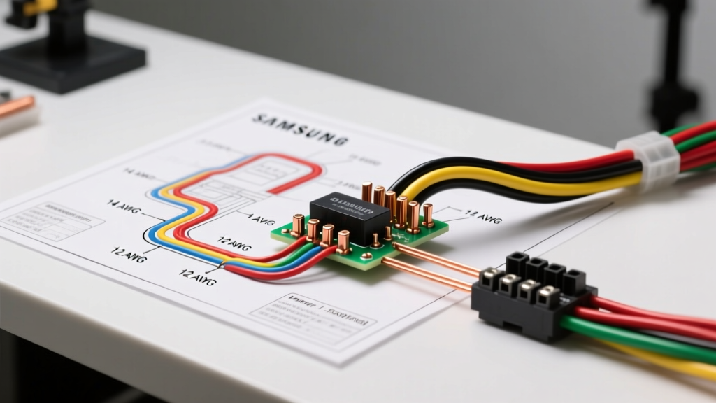
Wire Gauge & Ampacity Reference Table
| Wire Gauge (AWG) | Max Ampacity | Insulation Type | Application in Samsung Dryer |
|---|---|---|---|
| 10 AWG | 30 Amps | THHN / XHHW-2 | Main 4-prong power cord (L1, L2, Neutral, Ground) |
| 12 AWG | 20 Amps | Fiberglass / Teflon | Internal heating element leads, main heater relays |
| 14 AWG | 15 Amps | High-Temp PVC / Silicone | Thermal fuse routing, cycling thermostat, motor circuits |
| 18 AWG | 5 Amps | Standard PVC | Low-voltage sensor lines (thermistor, moisture sensors) |
The main terminal block on the back of a Samsung dryer requires a 10 AWG cord connected to a dedicated 30-amp double-pole breaker. Never substitute 12 AWG wire for the main supply, as the continuous draw of the heating element (typically 22 to 26 amps) will cause 12 AWG wire to overheat, violating National Electrical Code (NEC) Article 210 standards for branch circuits.
Decoding Internal Harness Color Codes
Samsung utilizes a specific color-coding schema for its internal wiring harnesses. Misinterpreting these colors when rerouting wires around the heating element housing is a common cause of post-repair control board failures. Below is the standard color code reference for Samsung electric dryer heating circuits:
- Red Wire: Carries 120V from L1 to the main control board relay and eventually to the heating element assembly.
- Black Wire: Carries 120V from L2. In the heating circuit, this typically routes through the motor centrifugal switch before reaching the heater assembly.
- White Wire: Neutral return. Used primarily for 120V control circuits, timers, and the drum motor. It does not carry current for the 240V heating element itself.
- Blue Wire: Often used for the motor circuit and control board signaling. You will see blue wires connecting the centrifugal switch to the heater relay.
- Orange / Yellow Wire: High-temperature switch legs. These wires route from the control board heater relay directly to the thermal fuse and high-limit thermostat mounted on the heating element housing.
The Role of the Centrifugal Switch
A critical safety feature in the Samsung wiring diagram is the integration of the drive motor's centrifugal switch. The heating element will only receive the full 240V potential (L1 and L2) when the drum is physically spinning. If the motor stops, the switch opens the L2 black wire circuit, instantly cutting power to the heating element to prevent a fire. When replacing the element, ensure the spade connectors on the orange and black wires are crimped tightly; loose connections here create high-resistance arcs that melt the plastic harness plugs.
Step-by-Step Heating Element Wiring & Replacement
Replacing the heating element requires careful attention to the wire routing path. The wires must not touch the bare metal of the exhaust duct or the heating coil housing.
- Access the Element: Remove the top panel (two rear screws), then the control panel, and finally the front bulkhead. The heating element housing (DC97-14486A) is located in the lower right quadrant.
- Document the Wiring: Before disconnecting anything, take a high-resolution photo of the terminal connections. Pay specific attention to the thermal fuse and the high-limit thermostat, as they are wired in series.
- Test Before Replacing: Use a multimeter set to Ohms (Ω). Probe the two main terminals on the heating coil. A healthy Samsung element reads between 9.0 and 11.0 ohms. If it reads infinite (OL), the coil is broken.
- Remove the Assembly: Remove the mounting screws securing the duct housing. Gently pull the assembly out, guiding the 12 AWG and 14 AWG wires through the chassis cutouts.
- Transfer Components (If Necessary): If your replacement part is just the coil (DC47-00019A) and not the full housing, carefully uncrimp the high-temp spade connectors from the old coil and attach them to the new one. Use a proper ratcheting crimp tool; pliers will result in a loose connection.
- Re-route and Secure: Seat the new housing. Ensure the orange and black wires are routed through the designated plastic loom channels to prevent them from vibrating against the hot metal ductwork.
Diagnostic Resistance Chart for Heating Circuit Components
When the wiring diagram indicates a path through multiple safety thermostats, a failure anywhere in the series will result in no heat. Use this reference chart to isolate the fault using a multimeter.
| Component | Location on Housing | Expected Resistance (Ohms) | Failure Symptom |
|---|---|---|---|
| Heating Coil | Inside main duct | 9.0 - 11.0 Ω | No heat, breaker trips instantly if shorted to ground |
| Thermal Fuse | Top of element housing | ~0.1 Ω (Continuity) | No heat, dryer runs but blows cold air |
| High-Limit Thermostat | Side of element housing | ~0.1 Ω (Continuity) | No heat, usually blows due to restricted venting |
| Cycling Thermostat | Blower housing (front) | ~0.1 Ω (Continuity) | Overheating, clothes scorching, or short cycles |
| Thermistor | Blower housing (front) | ~10,000 Ω (at 77°F) | Error codes (e.g., tE), erratic temperature control |
Pro Tip: If your thermal fuse tests open (OL), do not simply replace it. A blown thermal fuse is a symptom, not the root cause. Inspect the exterior vent hood for lint blockages and verify that the cycling thermostat is opening correctly to regulate the internal temperature.
NEC Compliance, Grounding, and Final Safety Checks
Proper grounding is non-negotiable when working with 240V appliance wiring diagrams. Modern Samsung dryers utilize a 4-prong NEMA 14-30 receptacle configuration, which separates the neutral (current-carrying) conductor from the equipment grounding conductor. According to NEC Article 250, the chassis of the dryer must be bonded exclusively to the green/bare ground wire, never to the white neutral wire.
When reassembling the terminal block on the rear of the dryer, ensure the strain relief clamp is tightened securely over the outer jacket of the 10 AWG power cord. If the cord is pulled, the tension must be absorbed by the jacket, not the internal copper conductors. For comprehensive schematic downloads and model-specific bulletins, technicians should consult the official Samsung Support portal or refer to the tech sheet hidden inside the dryer's control panel housing.
By strictly adhering to the correct wire gauges, respecting the internal color codes, and verifying continuity across the safety series, you ensure the heating element operates efficiently and safely for years to come.