
Understanding the RV Wiring Diagram for a Water Heater
When residential electricians transition to RV or camper van builds, the most common point of confusion is the water heater. Unlike a standard home unit that runs strictly on 240V or 120V AC, finding a reliable wiring diagram for a water heater in an RV reveals a complex, dual-voltage architecture. As of 2026, while high-end motorhomes are experimenting with 48V DC systems, the vast majority of travel trailers, fifth wheels, and camper vans still rely on the industry-standard 12V DC and 120V AC split configuration.
This guide breaks down the exact wiring schematics for the most prevalent RV water heaters on the market, specifically focusing on the ubiquitous Suburban SW6DE and the newer Nautilus NW6S series by Airxcel. We will cover the 12V DC gas ignition circuit, the 120V AC electric heating element circuit, wire gauge requirements, and actionable troubleshooting steps backed by RVIA and NFPA standards.
The Dual-Voltage Architecture: Gas vs. Electric
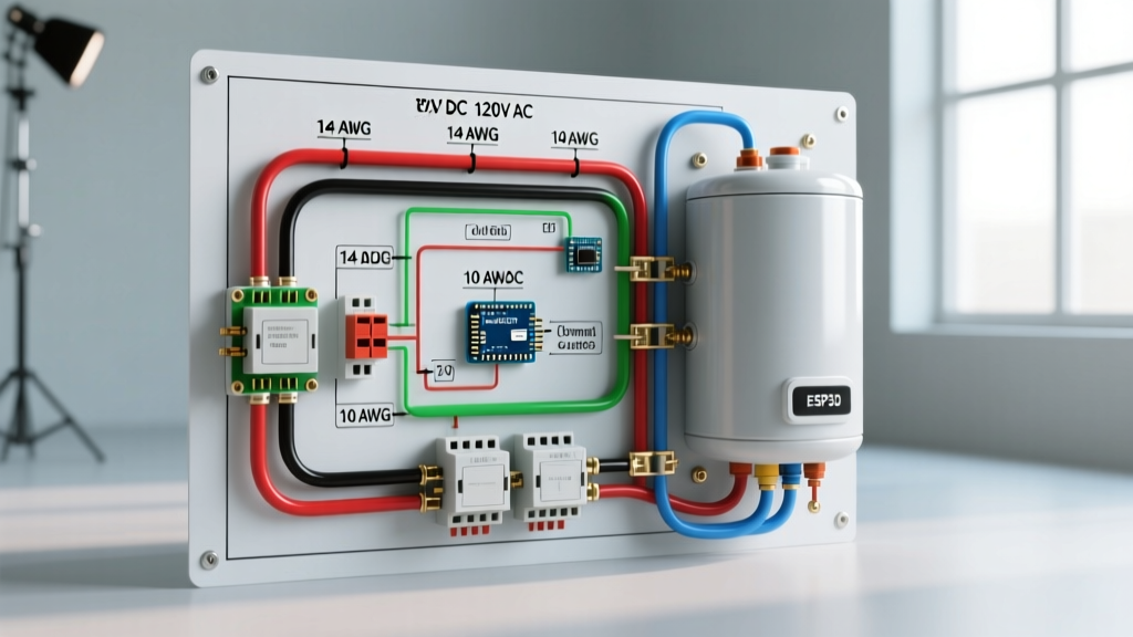
RV water heaters are designed for off-grid versatility. They feature two entirely separate electrical systems housed within the same unit:
- 12V DC System: Powers the control board, thermostat, and the high-voltage spark electrode used to ignite the propane gas burner. This allows you to heat water while boondocking using your camper’s lithium or AGM house battery bank.
- 120V AC System: Powers a 1440W immersion heating element. This is used when connected to shore power or running a sufficiently sized generator, preserving your propane supply.
Code Compliance Note: According to the NFPA 1192 Standard on Recreational Vehicles, all 120V AC circuits in an RV must be protected by a dedicated overcurrent device and routed separately from 12V DC low-voltage lines to prevent electromagnetic interference and fire hazards.
1. The 12V DC Ignition and Control Board Circuit
The 12V side of the wiring diagram for a water heater is responsible for logic and ignition. When you flip the 12V water heater switch on your RV’s command panel, a 12V signal is sent to the Suburban control board (typically part number 520884 or the newer 521000 series).
Key Wiring Specifications:
- Wire Gauge: 14 AWG stranded copper wire is standard for the 12V run from the DC fuse panel to the water heater.
- Overcurrent Protection: A dedicated 10A or 15A DC automotive blade fuse.
- Voltage Drop: The control board requires a minimum of 10.5V DC to open the gas solenoid valve and fire the spark electrode. If your wire run exceeds 15 feet, upgrade to 12 AWG stranded wire to mitigate voltage drop.
- The Spark Electrode: The control board sends a high-voltage pulse to the ceramic electrode. The gap between the electrode tip and the ground strap must be exactly 1/8 inch (3.2mm). If this gap widens due to vibration or carbon buildup, the board will click rapidly but fail to ignite the gas.
2. The 120V AC Electric Element Circuit
The 120V AC side is remarkably simple but carries a high amperage load. The standard Suburban 120V immersion element is rated at 1440 Watts. Using Ohm’s Law (Watts / Volts = Amps), a 1440W element at 120V draws exactly 12 Amps.
Key Wiring Specifications:
- Wire Gauge: 12 AWG solid or stranded copper (THHN/THWN rated) is mandatory. Never use 14 AWG for this circuit, as the continuous 12A draw will cause the wire to overheat over time.
- Overcurrent Protection: A dedicated 15A AC circuit breaker in the RV’s main load center.
- High-Limit Switch (ECO): The 120V hot wire passes through an Emergency Cut-Off (ECO) thermostat before reaching the element. If the water temperature exceeds 180°F, this bi-metallic switch physically snaps open, cutting power to the element to prevent a boiler explosion.
Wire Gauge and Overcurrent Protection Matrix
Use the following matrix to ensure your RV or camper van build meets the RVIA RV Safety Guidelines for water heater installations.
| Circuit Type | Function | Wire Gauge (Copper) | Breaker / Fuse | Max Continuous Draw |
|---|---|---|---|---|
| 12V DC | Control Board, Gas Solenoid, Spark | 14 AWG (12 AWG if >15ft) | 10A or 15A DC Fuse | 1.5A (during spark) |
| 120V AC | Electric Immersion Element | 12 AWG | 15A AC Breaker | 12.0 Amps |
| 12V DC (Switch) | Interior LED Indicator / Toggle | 18 AWG or 16 AWG | Inline 2A Fuse | 0.05 Amps |
Step-by-Step Wiring Procedure
Whether you are replacing a faulty harness or wiring a new camper van build from scratch, follow this sequence to ensure a safe, code-compliant installation. For detailed schematic PDFs, always refer to the Airxcel Suburban RV Support and Manuals portal.
- Isolate All Power: Disconnect the negative terminal of your RV house battery and unplug the 120V shore power cord. Verify zero voltage at the water heater terminals using a multimeter.
- Route the 120V AC Line: Run 12 AWG Romex or THHN wire from a dedicated 15A single-pole breaker in your AC load center to the water heater access panel. Keep this AC wire at least 2 inches away from any 12V DC wiring to prevent inductive noise.
- Terminate the AC Element: Connect the 120V Hot (Black) wire to the top terminal of the ECO high-limit switch. Run a jumper wire from the bottom ECO terminal to the top terminal of the upper thermostat. Connect the bottom thermostat terminal to the heating element. Connect the Neutral (White) wire directly to the other side of the heating element. Bond the Ground (Bare/Green) to the heater’s metal chassis.
- Wire the 12V DC Harness: Connect the 14 AWG Red wire to a 12V fused bus bar. Connect the Black wire to a clean, bare-metal chassis ground. Plug the 3-pin or 4-pin connector into the Suburban control board.
- Test the System: Reconnect the battery and shore power. Turn on the 12V gas switch and listen for the 3-second spark sequence followed by the “whoosh” of the gas igniting. Turn on the 120V AC switch and use a clamp meter on the AC hot wire to verify a 12A draw.
Troubleshooting Common Electrical Failures
Even with a perfect wiring diagram for a water heater, components fail due to the harsh vibrations and moisture inherent in RV travel. Here is how to diagnose the most common edge cases in 2026:
Failure Mode 1: Rapid Clicking, But No Gas Ignition
The Symptom: You turn on the 12V switch. The control board clicks rapidly for 15 seconds, the red fault LED illuminates, but the propane never lights.
The Fix: This is rarely a bad board. First, check your 12V DC ground. A poor chassis ground will provide enough voltage to run the logic board, but not enough amperage to fire the high-voltage spark coil. Second, inspect the ceramic spark electrode. If the ceramic is cracked, the spark will ground out against the burner tube instead of jumping the 1/8-inch gap. Replacement electrodes cost roughly $15 to $25.
Failure Mode 2: 120V AC Breaker Trips Instantly
The Symptom: You flip the 120V water heater breaker on, and it immediately trips to the OFF position.
The Fix: You have a dead short, almost certainly caused by a burnt-out immersion element. Over time, the internal nichrome wire breaks and touches the outer copper sheath, grounding the 120V directly to the tank. Disconnect power, remove the two wires from the element, and set your multimeter to Ohms (Ω). A healthy 1440W element will read between 10 and 12 Ohms. If it reads 0.0 Ohms or OL (Open Line), the element is dead. A replacement Suburban 120V element costs between $18 and $30 and requires a 1-1/16 inch deep socket for removal.
Failure Mode 3: Water Gets Scalding Hot, Then Shuts Down
The Symptom: The electric element heats the water to near-boiling, then stops working entirely and will not reset.
The Fix: The 180°F ECO (Emergency Cut-Off) switch has tripped. This happens if the primary 130°F thermostat welds itself closed and fails to cycle off. The ECO is a non-resettable, one-time-use safety fuse. You must replace the entire ECO/Thermostat bank (approx. $45) and inspect the control board relay for welding.
Final Safety and Maintenance Directives
Wiring an RV water heater requires strict adherence to both DC and AC safety protocols. Always use marine-grade, tinned copper wire for the 12V DC side if your camper van or travel trailer will be exposed to high humidity or coastal environments, as untinned copper will corrode and cause voltage drops at the crimp terminals. Furthermore, never bypass the 180°F ECO high-limit switch to restore power to a faulty heating element; doing so violates NFPA 1192 standards and creates a severe risk of catastrophic tank rupture. By following this wiring diagram for a water heater and respecting the dual-voltage boundaries, you ensure reliable hot water for years of off-grid exploration.