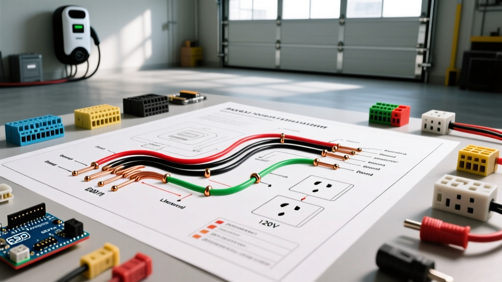

Decoding the Modern Wiring Diagram for Garage Appliances
The modern garage has evolved from a simple vehicle storage space into a high-demand workshop and EV charging hub. When interpreting a wiring diagram for garage setups, electricians and advanced DIYers must account for heavy inductive loads, continuous duty cycles, and strict National Electrical Code (NEC) mandates. As of 2026, local adoptions of the NEC require Ground Fault Circuit Interrupter (GFCI) protection on virtually all garage receptacles, fundamentally changing how we design appliance circuits.
This comprehensive guide breaks down the anatomy of a garage subpanel, provides a load calculation matrix, and delivers a step-by-step tutorial for wiring 240V heavy appliances like EV Level 2 chargers, 5HP air compressors, and MIG welders.
Anatomy of a Garage Subpanel Wiring Diagram
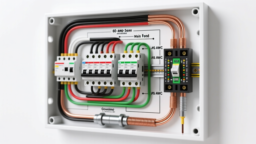
A robust garage wiring diagram begins at the main service panel and feeds a dedicated subpanel. For a fully equipped workshop, a 100-amp subpanel is the minimum recommended standard. The NFPA 70 (National Electrical Code) dictates that subpanels must maintain strictly isolated neutral and ground bus bars.
Feeder Cable Selection and Sizing
To feed a 100A subpanel located up to 100 feet from the main panel, standard practice in 2026 utilizes 3 AWG copper THHN/THWN wires pulled through 1.5-inch PVC or EMT conduit, or a pre-assembled 4-4-4-6 Aluminum SER (Service Entrance) cable. Copper offers superior conductivity and lower voltage drop, but aluminum SER remains a cost-effective alternative for short runs, provided you use antioxidant paste and torque lugs to manufacturer specifications (typically 45 in-lbs for 4 AWG aluminum).
120V General Purpose vs. Dedicated Appliance Circuits
General workbench receptacles should be wired on 20-amp circuits using 12 AWG copper wire. Under current NEC Article 210.8(A)(2), all 125V to 250V, single-phase, 15A to 50A receptacles in garages require GFCI protection. Instead of using bulky GFCI receptacles that can fail prematurely in unconditioned garage environments, modern wiring diagrams specify standard 20A GFCI circuit breakers (e.g., Square D HOM220GFIC, retailing around $115) installed in the subpanel.
240V Heavy Appliance and EV Charger Circuits
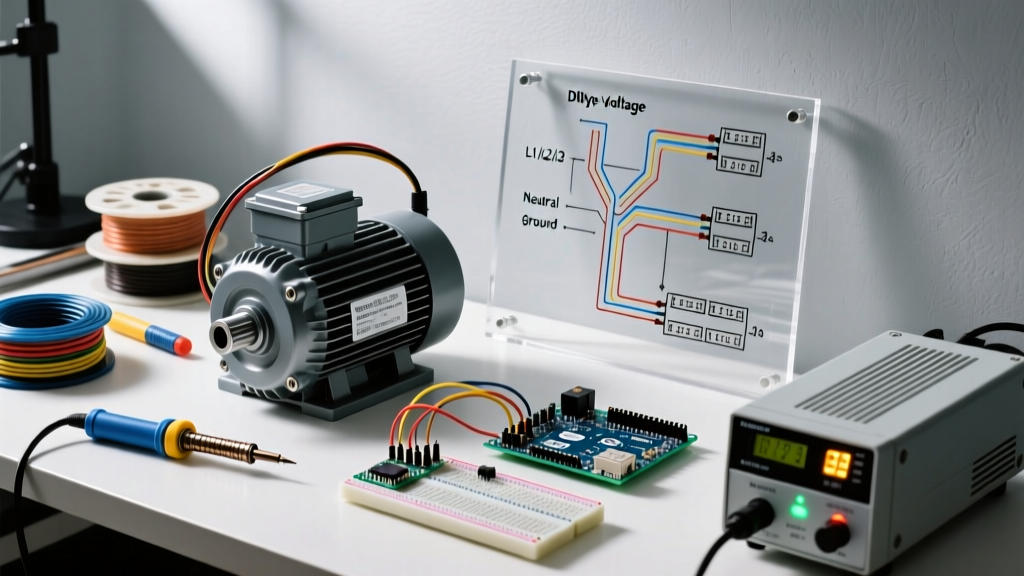
Heavy appliances demand dedicated 240V circuits. A critical distinction in your wiring diagram is the choice between NEMA 14-50 (4-prong: two hots, neutral, ground) and NEMA 6-50 (3-prong: two hots, ground). While older welders and compressors often used 6-50, modern EV chargers like the ChargePoint Home Flex or Tesla Wall Connector require a neutral wire for internal 120V logic boards, making the NEMA 14-50 the universal standard for new garage appliance installations.
Garage Appliance Load Calculation Matrix
Properly sizing your breakers and wire gauges prevents nuisance tripping and fire hazards. The table below outlines standard 2026 specifications for common garage appliances. Always apply the NEC 125% continuous load rule for EV chargers and space heaters.
| Appliance Type | Voltage / Phase | Max Amperage | Wire Gauge (Copper) | Breaker Size & Type | Est. Material Cost (2026) |
|---|---|---|---|---|---|
| Level 2 EV Charger (48A Continuous) | 240V / 1-Phase | 60A (Sized) | 4 AWG THHN | 60A 2-Pole GFCI | $210 (Breaker + Wire) |
| 5HP Air Compressor | 240V / 1-Phase | 28A (Inrush 80A) | 8 AWG THHN | 40A HACR Rated | $85 (Breaker + Wire) |
| 250A MIG Welder | 240V / 1-Phase | 45A | 6 AWG THHN | 50A 2-Pole | $105 (Breaker + Wire) |
| 24k BTU Mini-Split HVAC | 240V / 1-Phase | 15A | 12 AWG THHN | 20A 2-Pole | $65 (Breaker + Wire) |
| Workbench Receptacles (General) | 120V / 1-Phase | 16A | 12 AWG THHN | 20A Single-Pole GFCI | $135 (Breaker + Wire) |
Step-by-Step Tutorial: Wiring a 50A 240V Appliance Receptacle
Whether you are wiring a heavy-duty air compressor or a NEMA 14-50 EV charging outlet, the physical execution requires precision. Follow this workflow to ensure code compliance and operational safety.
Step 1: Subpanel Preparation and Breaker Seating
- De-energize the Subpanel: Shut off the main feeder breaker. Verify zero voltage using a CAT III or CAT IV multimeter (e.g., Fluke 117) across the bus bars.
- Install the Breaker: For a 50A circuit, snap in a 2-pole 50A breaker (e.g., Eaton BR250). Ensure the bus bar stabs are clean and free of debris.
- Land the Pigtails: If using a GFCI or AFCI breaker, terminate the neutral pigtail directly to the isolated neutral bar. Never land a neutral pigtail on the ground bar in a subpanel.
Step 2: Conduit Routing and Wire Pulling
Surface-mounted EMT (Electrical Metallic Tubing) is the preferred wiring method for garage walls, offering superior physical protection compared to exposed Romex (NM-B), which is prohibited by NEC Article 334.15 where subject to physical damage.
- Run 3/4-inch EMT from the subpanel to the appliance drop point.
- Pull four individual 6 AWG THHN/THWN copper conductors: Black (Hot 1), Red (Hot 2), White (Neutral, re-identified with black tape at both ends if used as a hot, but kept white for 14-50 neutral), and Green (Equipment Ground).
- Apply wire pulling lubricant (e.g., Ideal Yellow 77) to prevent insulation scoring on conduit bends.
Step 3: Terminating the NEMA 14-50 Receptacle
Use a heavy-duty, industrial-grade receptacle like the Leviton 279-S00. Avoid cheap residential-grade alternatives, as they often lack the internal mass to dissipate heat during continuous 40A EV charging loads, leading to melting faceplates.
Expert Torque Specification: The NEC (Article 110.14(D)) mandates the use of a calibrated torque screwdriver. For 6 AWG copper wire on a Leviton 14-50R, torque the terminal screws to exactly 50 in-lbs. Under-torquing causes arcing; over-torquing strips the brass threads.
Edge Cases and Common Failure Modes
Even with a perfect wiring diagram for garage layouts, real-world variables can introduce failures. Anticipate these edge cases:
1. Motor Inrush Current Nuisance Tripping
A 5HP air compressor drawing 25A running amps can experience an inrush current of 100A+ upon startup. If your wiring diagram specifies a standard thermal-magnetic breaker, it may trip instantly. Solution: Always specify HACR (Heating, Air Conditioning, and Refrigeration) rated breakers for motorized garage appliances. These breakers feature a magnetic trip delay calibrated to absorb inrush spikes.
2. Voltage Drop on Long Conduit Runs
If your detached garage subpanel is located 150 feet from the main house panel, a 6 AWG wire on a 50A circuit will experience a voltage drop exceeding the recommended 3% threshold. This causes EV chargers to throttle amperage and welders to run hot. Solution: Upsize the feeder and branch circuit wires by one gauge (e.g., use 4 AWG instead of 6 AWG) for any run exceeding 100 feet.
3. Neutral-to-Ground Bonding Errors
The most dangerous mistake in garage subpanel wiring is failing to remove the green bonding screw that ships pre-installed on the neutral bus bar. If the neutral and ground are bonded in the subpanel, return current will travel back to the main panel via both the neutral wire and the equipment grounding conductor, electrifying the garage conduit and creating a severe shock hazard. Always isolate the neutral bar in a subpanel.
NEC Compliance and Safety Standards
Designing a safe garage electrical system requires strict adherence to national standards. According to the U.S. Department of Energy's EV Charging Guidelines, hardwiring Level 2 chargers is increasingly recommended over plug-in NEMA 14-50 receptacles to eliminate GFCI nuisance tripping issues inherent to some EVSE internal sensors conflicting with panel-level GFCI breakers.
Furthermore, always consult your local Authority Having Jurisdiction (AHJ). Many municipalities in 2026 require an arc-fault (AFCI) and ground-fault (GFCI) dual-function breaker for all 120V garage lighting and receptacle circuits, pushing the material cost of standard 15A circuits to approximately $65 per breaker. By integrating these specifics into your wiring diagram for garage projects, you ensure a system that is not only functional for today's heavy appliances but fully compliant with modern electrical safety codes.