
Understanding the Intertherm Electric Furnace Wiring Diagram
Intertherm electric furnaces, now manufactured under the Nortek Global HVAC umbrella, remain the industry benchmark for manufactured and mobile home heating. Unlike gas systems, electric furnaces rely entirely on high-amperage resistance heating elements, drawing massive continuous current. Understanding the Intertherm electric furnace wiring diagram is not merely about connecting internal control wires; it is fundamentally about integrating a heavy, continuous electrical load into your main breaker panel safely and in compliance with the National Electrical Code (NEC).
Whether you are upgrading an aging mobile home panel or troubleshooting a failed heating element, this guide breaks down the schematic logic, breaker sizing, wire gauge requirements, and critical panel integration strategies for 2026 installations.
Anatomy of the Schematic: High-Voltage vs. Low-Voltage Circuits
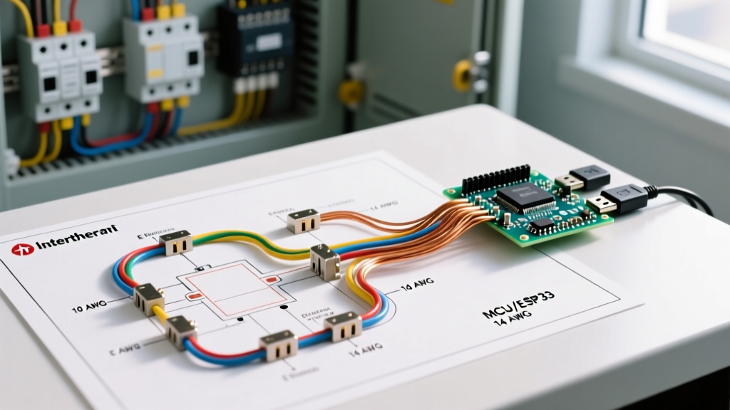
The wiring schematic for popular Intertherm models (such as the E5EH, E6EH, and M1 series) divides into two distinct electrical pathways:
- The 240V High-Voltage Power Circuit: This feeds the main heating elements (typically configured in 5kW strips) and the blower motor. It originates at the main electrical panel, passes through a local disconnect, and terminates at the furnace's main junction block.
- The 24V Low-Voltage Control Circuit: Powered by a step-down transformer, this circuit controls the thermostat, sequencers, relays, and safety limit switches.
The Role of the Sequencer
The heart of the Intertherm wiring diagram is the sequencer. When the thermostat calls for heat, it sends 24V to the sequencer coil. This coil heats a bimetallic strip, which physically closes the high-voltage contacts to energize the heating element. Simultaneously, a secondary contact closes to start the blower motor. This engineered delay (usually 10 to 15 seconds) prevents the system from blowing cold air into the living space before the elements reach operating temperature.
Breaker Sizing and Wire Gauge Selection Matrix
Sizing the breaker and wire correctly is the most critical step in panel integration. Undersized wires will overheat, while oversized breakers will fail to protect the circuit. Below is the definitive sizing matrix for common Intertherm electric furnaces, based on NEC Article 240 and standard 75°C terminal ratings.
| Intertherm Model | kW Rating | Max Amp Draw | Breaker Size (240V) | Copper Wire Gauge (THHN) | Aluminum Wire Gauge (XHHW) |
|---|---|---|---|---|---|
| M1-056 | 5.6 kW | 23.3 A | 30 A | 10 AWG | 8 AWG |
| E5EH-015 | 15.0 kW | 62.5 A | 70 A | 4 AWG | 2 AWG |
| E6EH-020 | 20.0 kW | 83.3 A | 90 A | 2 AWG | 1/0 AWG |
| V5AH-023 | 23.0 kW | 95.8 A | 100 A | 1 AWG | 2/0 AWG |
Expert Note: Intertherm furnaces are considered continuous loads if they run for 3 hours or more. However, NEC Article 424.3(B) specifies that branch-circuit conductors and overcurrent devices for fixed electric space heating equipment must be sized at 125% of the total load. The breaker sizes in the table above already account for this 125% continuous load multiplier.
Panel Capacity and Load Calculations for Mobile Homes
Mobile home electrical panels are notoriously constrained. A standard 100-amp main panel cannot safely support a 20kW Intertherm furnace (drawing 83.3 amps) alongside a 4500W electric water heater, an electric range, and general lighting. If you attempt this, the main breaker will trip continuously during peak winter usage.
Performing the NEC Article 220 Load Calculation
Before pulling wire from the panel, you must perform a standard NEC Article 220 load calculation. For a 20kW furnace, you are consuming over 80% of a 100-amp panel's total capacity just on heating.
- Upgrade the Service: For any Intertherm furnace rated 15kW or higher, a 200-amp main service upgrade is highly recommended. Expect to pay between $1,800 and $3,500 for a full mobile home service upgrade in 2026, depending on local utility requirements and trenching distances.
- Implement Load Shedding: If a panel upgrade is impossible, install an automatic load-shedding relay (such as the Intermatic ET1125). This device monitors the total current and temporarily cuts power to the water heater when the furnace sequencers engage, preventing main breaker trips.
Aluminum vs. Copper Wiring: Termination Best Practices
Many older manufactured homes utilize aluminum branch wiring to save costs. While aluminum is perfectly safe when installed correctly, it is highly susceptible to thermal expansion and oxidation, which can lead to loose connections and catastrophic arc faults at the furnace junction block.
- Use Anti-Oxidant Paste: If terminating aluminum wire at the Intertherm disconnect or furnace lugs, you must apply a UL-listed anti-oxidant compound (such as Noalox or Penetrox E) to the stripped conductor. This prevents aluminum oxide buildup, which acts as an electrical insulator and causes extreme heat.
- Torque Specifications: Do not guess the tightness of the lug screws. Use a calibrated torque screwdriver. Most Intertherm terminal blocks require between 35 and 45 inch-pounds of torque. Over-tightening will cold-flow the aluminum and result in a loose connection within months; under-tightening will cause immediate arcing.
- COPALUM or AlumiConn Connectors: If you are splicing copper pigtails to existing aluminum wiring inside the furnace compartment, never use standard wire nuts. Use AlumiConn lug connectors or King Innovation AlumiCrimp connectors to bridge the dissimilar metals safely.
Step-by-Step Panel Integration and Disconnect Installation
According to the National Fire Protection Association (NFPA 70), specifically NEC Article 424.19, a means for simultaneously disconnecting all ungrounded conductors must be provided within sight of the furnace. Here is the professional workflow for installation:
- Install the Fused Disconnect: Mount a 240V pull-out or fused disconnect switch on the wall adjacent to the Intertherm unit. For a 20kW unit, use a 60A or 100A disconnect housing with appropriately rated fuses or a solid pull-out block.
- Pull the Feeder Wire: Run the appropriately sized THHN/THWN conductors (plus a ground) through 3/4-inch or 1-inch EMT conduit from the main panel to the disconnect. Ensure the ground wire is sized per NEC Table 250.122 (e.g., an 8 AWG copper ground for a 100A breaker).
- Wire the Disconnect to the Furnace: Use flexible metallic conduit (FMC) or liquid-tight flexible metal conduit (LFMC) for the final whip connecting the disconnect to the furnace knockouts. This isolates the furnace vibration from the rigid wall conduit.
- Verify Grounding and Bonding: Ensure the equipment grounding conductor is bonded to the furnace chassis and the disconnect box. Mobile homes require a rigorous grounding path back to the main panel ground bar to ensure breakers trip during a ground fault.
Common Wiring Failures and Advanced Troubleshooting
When an Intertherm furnace fails to produce heat, or the breaker trips immediately, the issue usually traces back to one of three specific electrical failures. According to data from the U.S. Department of Energy, improper electrical maintenance is a leading cause of HVAC inefficiency and failure.
1. Sequencer Contact Welding
Symptom: The furnace blows cold air when the thermostat is off, or the heating elements stay red-hot continuously, eventually tripping the high-limit switch or the main breaker.
Cause: The high inrush current of the heating elements can cause the internal contacts of the sequencer to weld together in the closed position.
Fix: Replace the faulty sequencer. Sequencers are model-specific (e.g., Honeywell or White-Rodgers replacements rated for the specific kW load). Expect to pay $25 to $45 for a replacement part. Always replace sequencers in pairs if they share the same age and wear profile.
2. Step-Down Transformer Burnout
Symptom: The blower runs, but no heat is produced. The thermostat display is dead.
Cause: A short in the 24V control wiring (often caused by a frayed thermostat wire touching the chassis ground) blows the transformer's internal fuse or burns out the secondary coil.
Fix: Test the transformer secondary with a multimeter; it should read exactly 24V AC. If it reads 0V, replace the 40VA transformer. Before powering up the new transformer, use the multimeter's continuity setting to find and repair the 24V short, or the new transformer will blow immediately.
3. High-Limit Switch Tripping
Symptom: The furnace heats up, but shuts off prematurely after 2 to 3 minutes. The reset button on the limit switch pops.
Cause: While this can be a wiring issue, it is most often an airflow restriction causing the elements to overheat. A clogged filter, failing blower capacitor, or collapsed mobile home flex-duct will trigger the limit switch.
Fix: Check the blower motor capacitor (usually a 5 MFD or 7.5 MFD run capacitor). If the blower is spinning slowly, replace the capacitor ($12 to $18). Ensure the air filter is clean and all duct collars are sealed with mastic to prevent air leakage inside the furnace cavity.
Final Safety and Compliance Checklist
Before energizing the system for the first time, verify the following:
- All high-voltage terminal screws are torqued to manufacturer specifications.
- The 24V control wires are routed away from the 240V lines to prevent electromagnetic interference with smart thermostats.
- The main panel breaker is correctly labeled as 'Electric Furnace' with the exact amperage noted.
- The furnace chassis is properly bonded to the mobile home's grounding electrode system.
By strictly adhering to the Intertherm electric furnace wiring diagram and respecting the massive electrical load these units demand, you ensure a safe, efficient, and code-compliant heating system that will reliably protect your home through the harshest winters.