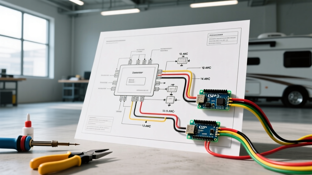

Understanding the Core Wiring Diagram for RV Converter Systems
Upgrading or replacing an RV power converter is one of the most impactful electrical projects you can undertake in a motorhome, travel trailer, or fifth wheel. The converter serves as the heart of your rig's 12-volt DC system, stepping down 120-volt AC shore power to safely charge your house batteries and run low-voltage appliances. In 2026, with the massive shift toward Lithium Iron Phosphate (LiFePO4) battery banks, understanding the exact wiring diagram for RV converter setups is more critical than ever. Lithium batteries can accept continuous charge rates that easily max out older 45-amp units, necessitating upgrades to 60-amp, 80-amp, or even 100-amp smart converters.
This comprehensive vehicle-specific guide breaks down the anatomy of modern RV converter wiring, provides exact wire gauge and breaker sizing matrices, and details the step-by-step installation protocol required to meet current National Electrical Code (NEC) Article 551 standards for recreational vehicles.
Anatomy of the RV Converter Wiring Diagram
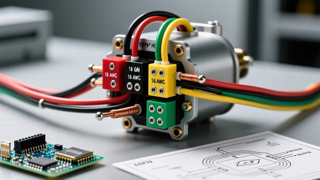
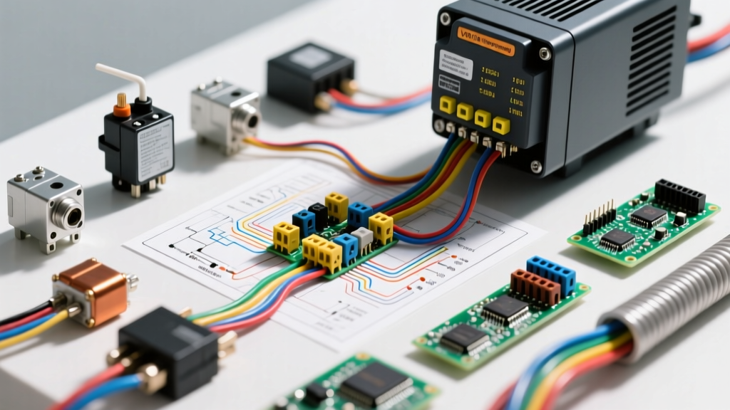
A standard RV converter/charger wiring diagram is divided into two distinct circuits: the 120V AC input stage and the 12V DC output stage. Miswiring either side can result in catastrophic failure, melted terminal blocks, or severe fire hazards.
1. The 120V AC Input Stage
The AC input draws power directly from your RV's main AC breaker panel. According to standard RVIA (RV Industry Association) guidelines, the converter must be on a dedicated 15-amp or 20-amp AC branch circuit.
- Black Wire (Hot): Connects to the dedicated 15A/20A single-pole AC breaker in the main distribution panel.
- White Wire (Neutral): Connects to the AC neutral bus bar. Never bond neutral to ground in an RV sub-panel.
- Green/Bare Wire (Ground): Connects to the AC grounding bus bar, which ultimately ties back to the shore power cord's grounding pin and the RV chassis.
2. The 12V DC Output Stage
The DC output supplies raw amperage to the 12V fuse panel and the house battery bank. This is where voltage drop calculations become paramount.
- Red Wire (Positive): Routes from the converter's positive terminal, through a primary DC circuit breaker or fuse, to the positive bus bar or directly to the battery bank positive terminal.
- White Wire (Negative): Routes from the converter's negative terminal to the DC negative bus bar or the battery bank's shunt (if using a battery monitor).
Wire Gauge and Breaker Sizing Matrix (2026 Standards)
One of the most common failure modes in DIY RV electrical work is undersizing the DC wiring. Converters operate at high continuous loads. Per NFPA 70 (NEC) continuous load rules, wiring and overcurrent protection must be rated for 125% of the converter's maximum output.
| Converter Rating | Max Continuous Load (80%) | DC Wire Gauge (<10 ft run) | DC Wire Gauge (10-15 ft run) | Required DC Breaker Size |
|---|---|---|---|---|
| 45 Amp (e.g., WFCO WF-8945) | 36 Amps | 8 AWG Copper | 6 AWG Copper | 50A DC Breaker |
| 60 Amp (e.g., PD9260) | 48 Amps | 6 AWG Copper | 4 AWG Copper | 70A DC Breaker |
| 80 Amp (e.g., PD9280) | 64 Amps | 4 AWG Copper | 2 AWG Copper | 90A DC Breaker |
| 100 Amp (e.g., Victron/Inverter-Charger) | 80 Amps | 2 AWG Copper | 1/0 AWG Copper | 125A DC Breaker |
Note: Run length is measured as the total round-trip distance (positive + negative wire combined). Always use stranded, pure copper marine-grade wire (THHN/THWN or UL 1426) rather than copper-clad aluminum (CCA).
Step-by-Step Installation Protocol
Follow this exact sequence to ensure a safe, code-compliant installation. For this guide, we are referencing the installation of a popular 2026 upgrade model, the Progressive Dynamics PD9280 80-amp smart converter.
Step 1: Lockout / Tagout and Verification
Disconnect the RV from shore power and turn off the inverter (if equipped). Disconnect the negative terminal of the house battery bank. Use a non-contact voltage tester and a digital multimeter to verify 0V AC at the converter's input terminals and 0V DC at the output terminals.
Step 2: AC Input Wiring and Torque
Strip 3/8 inch of insulation from the 12 AWG or 10 AWG AC wires. Insert them into the converter's AC terminal block. Using a calibrated torque screwdriver, tighten the terminal screws to the manufacturer's specification—typically 35 to 45 inch-pounds. Under-torquing causes arcing; over-torquing strips the brass threads.
Step 3: DC Output Crimping and Termination
For 4 AWG or 2 AWG DC wires, do not use solder. Solder creates a rigid joint that can fracture under the constant vibration of highway travel. Instead, use a closed-end copper ring terminal and a hex-crimp tool (such as the Knoweasy or Glarks heavy-duty crimpers). Apply adhesive-lined dual-wall heat shrink over the crimp barrel to prevent moisture intrusion and copper oxidation.
Step 4: Overcurrent Protection Placement
Install the primary DC circuit breaker (e.g., a 90A Blue Sea Systems MRBF terminal fuse or a magnetic hydraulic breaker) on the positive red wire. Per NEC and RVIA standards, this overcurrent device must be located within 18 inches of the battery positive terminal or the main positive bus bar, not at the converter end. This protects the entire wire run in the event of a short circuit.
2026 Lithium (LiFePO4) Upgrade Considerations
If you are upgrading your RV's house bank to LiFePO4 batteries in 2026, your wiring diagram for the RV converter must account for the battery's low internal resistance. Unlike lead-acid batteries, which naturally taper their charge acceptance as they near 80% capacity, lithium batteries will pull the maximum available amperage from the converter until they reach nearly 100% State of Charge (SoC).
This means a 60-amp converter will output a continuous 60 amps for hours. If your wiring is undersized, the voltage drop will trigger the converter's thermal protection, or worse, melt the terminal block. Furthermore, ensure your chosen converter has a selectable 'Lithium Charge Profile' (typically 14.4V to 14.6V bulk/absorption with no float stage). Standard lead-acid profiles with a 13.2V float and periodic equalization cycles will trigger a lithium battery's BMS (Battery Management System) overvoltage protection, causing the BMS to disconnect and potentially damaging the converter's diodes via load-dump voltage spikes.
Troubleshooting Matrix: Common Converter Failure Modes
Even with a perfect wiring diagram, environmental factors and component aging can cause issues. Use this diagnostic matrix to troubleshoot common RV converter anomalies.
| Symptom | Potential Cause | Diagnostic Step | Corrective Action |
|---|---|---|---|
| 12V lights flicker when high-draw DC appliances run | Severe voltage drop (>0.5V) on DC wiring | Measure DC voltage at converter terminals vs. battery terminals under load. | Upsize DC wire gauge (e.g., from 6 AWG to 4 AWG) and clean bus bar connections. |
| Converter cooling fan runs constantly, unit is hot to touch | Thermal throttling due to continuous LiFePO4 bulk charging | Check ambient temperature and verify converter amperage output with a DC clamp meter. | Upgrade to a higher-amperage converter (e.g., 80A) or improve compartment ventilation. |
| Loud 60Hz humming from the converter chassis | Failing filter capacitor or loose internal transformer lamination | Measure AC ripple on the DC output using a multimeter's AC voltage setting. | Replace the converter unit. (AC ripple >1.5V indicates failing filtering). |
| DC breaker trips immediately upon shore power connection | Reverse polarity on DC output or dead short to chassis | Disconnect battery. Use multimeter continuity mode between positive wire and RV chassis. | Verify red/white wire orientation. Inspect wire run for chafing against metal framing. |
Final Safety and Compliance Checks
Before restoring power, perform a final visual inspection of the wiring diagram for RV converter connections. Ensure no stray copper strands are protruding from terminal blocks, which could cause a short circuit. Verify that all DC wires are secured with nylon cable ties every 18 inches to prevent chafing against the RV's aluminum or steel frame during transit.
Reconnect the house battery bank first, then restore AC shore power. Use a digital multimeter to verify the DC output voltage at the battery terminals. For a lithium profile, you should see 14.4V; for a standard AGM/Gel profile, expect 13.6V to 14.4V depending on the charge stage. By adhering to these precise wiring standards and utilizing correctly sized components, your RV's electrical system will remain safe, efficient, and ready for off-grid boondocking for years to come.