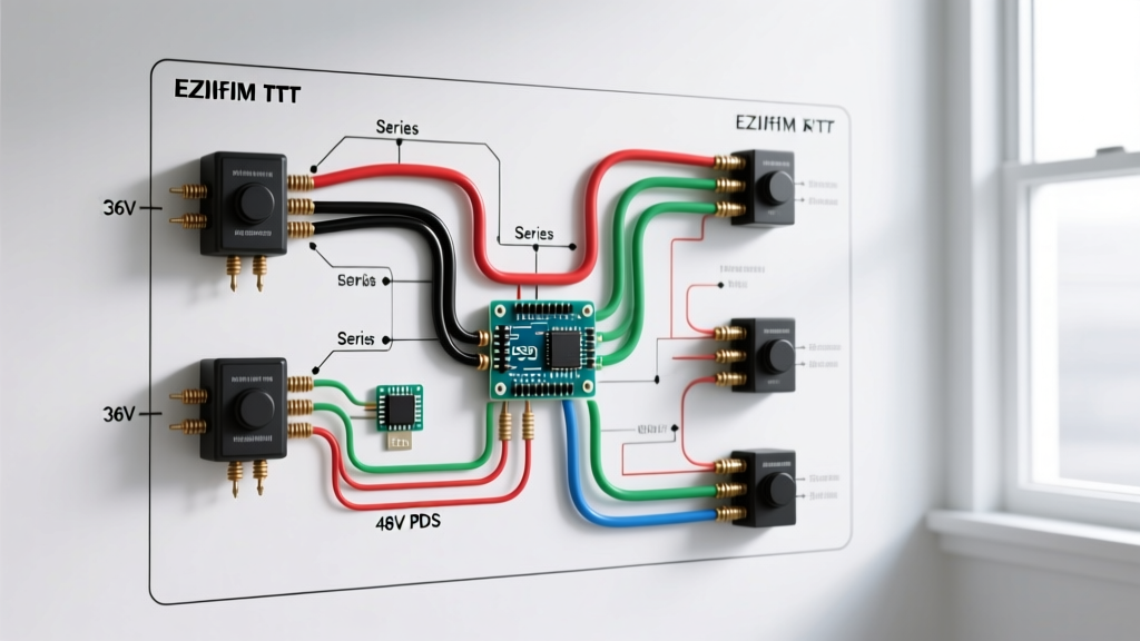

Understanding the EZGO TXT Electrical Architecture
The E-Z-GO TXT platform remains one of the most ubiquitous golf carts in the world, with production spanning from 1994 through 2013. Because the TXT generation covers nearly two decades of engineering evolution, a single 'wiring diagram for EZGO TXT' does not exist. Instead, the electrical architecture is divided into four distinct eras: the 36V Series (1994-1995), the 36V DCS (1996-2000), the 48V PDS (2000-2010), and the 48V Freedom (2011-2013). Understanding which schematic applies to your specific serial number is the critical first step in any diagnostic or modification procedure.
⚠️ High-Current Safety Warning: The main battery cables in a TXT carry upwards of 300 to 400 amps under heavy load. Always disconnect the primary negative battery cable and place the Tow/Run switch in the 'TOW' position before probing any controller or solenoid terminals to prevent accidental rollaways or arc flashes.Core Variations: Series, DCS, PDS, and Freedom
Before tracing wires, you must identify your drive system. The wiring diagram for EZGO TXT models changes drastically depending on the motor and controller configuration. Below is a structural comparison of the four primary electrical systems.
| System Type | Voltage | Motor Type | Throttle Input | Key Schematic Feature |
|---|---|---|---|---|
| Series (Resistor) | 36V | Series-Wound | V-Glide (Potentiometer) | Field weakening via resistor coils; 4 solenoids |
| DCS (Drive Control System) | 36V | Separately Excited (SepEx) | V-Glide (Potentiometer) | Regenerative braking; single main solenoid |
| PDS (Precision Drive System) | 48V | SepEx | ITS (Inductive Sensor) | On-Board Computer (OBC); programmable controller |
| Freedom | 48V | SepEx | ITS (Inductive Sensor) | High-speed motor; updated controller logic |
Decoding the Wiring Diagram for EZGO TXT (36V Series & DCS)
For older 36V models, the wiring harness relies heavily on mechanical switching and resistive feedback. The most complex portion of the 36V wiring diagram is the V-Glide assembly located under the driver's side cowl.
The V-Glide Potentiometer Circuit
The V-Glide uses a 0-5K ohm potentiometer to tell the controller how far the accelerator pedal is depressed. In the wiring diagram, you will trace three primary wires from the V-Glide to the controller:
- Black/White Tracer (18 AWG): 5V reference voltage from the controller.
- White/Black Tracer (18 AWG): Signal return (wiper). This voltage sweeps from roughly 0.8V (idle) to 3.6V (full throttle).
- Black (18 AWG): Sensor ground.
Failure Mode: The carbon track inside the V-Glide wears out over time, creating 'dead spots.' If your cart jerks or fails to accelerate smoothly, use a multimeter to check for infinite resistance drops while manually sweeping the V-Glide arm through its full arc.
Decoding the Wiring Diagram for EZGO TXT (48V PDS & Freedom)
The 48V PDS and Freedom models represent a massive leap in electrical complexity. The wiring diagram for these models centers around the Curtis 1268 controller and the On-Board Computer (OBC).
The Inductive Throttle Sensor (ITS) Loop
Unlike the resistive V-Glide, the 48V TXT uses an Inductive Throttle Sensor (ITS). This sensor contains a coil and a moving ferrite core. The controller sends a high-frequency alternating current (approx. 15kHz) to the ITS, and the sensor returns a modified signal based on the core's physical position. Because it relies on inductance rather than physical electrical contact, it is immune to the carbon-track wear that plagues the V-Glide.
The OBC and Charger Interlock
A unique feature of the PDS/Freedom wiring diagram is the integration of the OBC. The OBC monitors battery voltage and controls the onboard charger. It utilizes a 4-pin connector:
- Pin 1 (Yellow): Battery pack positive (monitors state of charge).
- Pin 2 (Black): Battery pack negative.
- Pin 3 (Blue): Charger positive (interlock circuit).
- Pin 4 (Red): Charger negative.
If the OBC detects a fault or a fully charged state, it opens the internal relay on the Blue wire, preventing the charger from activating. This is a critical node to test if your cart's batteries are not charging.
Common Failure Modes & Diagram-Based Troubleshooting
When your TXT refuses to move, the wiring diagram provides a logical path for isolation. Follow this exact sequence using a digital multimeter (DMM) to diagnose a 'dead cart' scenario.
Step 1: Solenoid Activation Test
The heavy-duty solenoid is the bridge between the battery pack and the controller. It has two large terminals (high current) and two small terminals (low current trigger).
- Set your DMM to DC Voltage.
- Place the black probe on the main battery negative and the red probe on the small 'trigger' terminal of the solenoid.
- Turn the key on and press the throttle. You should read full pack voltage (approx. 48V on a PDS, 36V on a Series).
- Diagnostic Result: If you read 0V, the fault is upstream (microswitches, OBC, or Tow/Run switch). If you read 48V but the solenoid does not click, the solenoid coil is open and requires replacement ($45-$85 for an OEM 48V coil).
Step 2: High-Current Voltage Drop Test
If the solenoid clicks but the cart does not move, the high-current contacts inside the solenoid may be pitted.
- Set your DMM to DC Voltage.
- Place the red probe on the large battery-side terminal and the black probe on the large controller-side terminal.
- Press the throttle (with the rear wheels jacked up safely).
- Diagnostic Result: A healthy solenoid will show a voltage drop of less than 0.2V under load. If you read 5V, 10V, or full pack voltage across the large terminals while engaged, the internal contacts are burned, and the solenoid must be replaced.
Upgrading the TXT Wiring Harness for 2026 Performance
As of 2026, the most common modification to the EZGO TXT platform is the conversion from lead-acid to LiFePO4 (Lithium Iron Phosphate) batteries. This upgrade fundamentally alters how you interact with the factory wiring diagram.
Bypassing the OBC for Lithium Conversions
Lithium batteries come with their own internal Battery Management System (BMS), which handles cell balancing, over-discharge protection, and charge termination. The factory OBC is designed specifically for the charging profile of lead-acid batteries and will actively interfere with a lithium BMS, often shutting off the charge prematurely.
Expert Wiring Tip: To bypass the OBC, you must rewire the charger interlock. Disconnect the Blue and Red wires from the OBC's 4-pin plug. Splice the Blue wire (charger positive) directly to the Red wire (charger negative) using a 14 AWG butt connector and heat shrink. This tricks the charger into turning on immediately when plugged in, allowing the lithium BMS to take over charge management. Always retain a high-amp fuse (150A) on the main positive line to protect the new harness.
Upgrading Wire Gauges for High-Torque Motors
If you are upgrading to a high-torque aftermarket motor (such as a Plum Quick or Navitas system), the factory 6 AWG battery cables will become a bottleneck, generating excessive heat and voltage drop. According to the National Electrical Code (NEC) guidelines for DC ampacity, continuous high-current draws require thicker conductors. Upgrade all main battery cables, solenoid lugs, and controller B+/M+ leads to 2 AWG or 1/0 AWG pure copper wire. Expect to spend between $120 and $180 on a complete custom 2 AWG cable kit with tinned copper lugs to minimize resistance.
Authoritative References & Further Reading
For exact pinouts, factory torque specifications, and serial-number-specific schematics, consult the following authoritative resources:
- E-Z-GO Official Owner Resources & Manuals Portal - Access factory service manuals and serial number lookup tools to identify your exact TXT generation.
- National Fire Protection Association (NFPA) - National Electrical Code (NEC) - Reference Article 480 for critical safety standards regarding battery installations, ventilation, and DC wire ampacity derating.