
Understanding the Dual-Voltage Architecture of RV AC Units
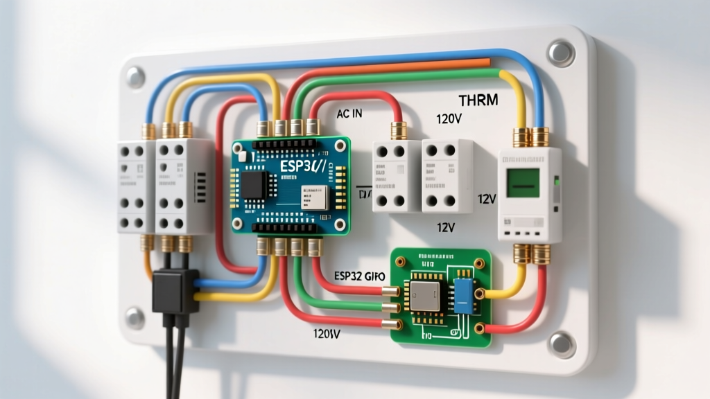
Unlike residential split-system HVAC units, recreational vehicle air conditioners operate on a unique dual-voltage architecture. When analyzing a wiring diagram for RV air conditioner systems, you are essentially looking at two completely separate electrical circuits that must interact flawlessly. The heavy lifting—powering the compressor and the blower motor—requires a 120V AC branch circuit. Meanwhile, the logic, thermostat communication, and control board relays operate on a 12V DC system derived either directly from the RV’s house battery bank or via a step-down transformer located inside the ceiling assembly.
Misinterpreting these circuits is the leading cause of blown control boards, tripped main panel breakers, and catastrophic compressor lockups. Whether you are upgrading to a Dometic BriskAir II (Model 3107205.021) or replacing a failing Coleman Mach 3 Plus (Model 48204C866), understanding the exact pinouts, wire gauge requirements, and voltage drop limitations is critical for a safe, code-compliant installation.
Standard 6-Pin Wiring Diagram for RV Air Conditioner Units
The communication bridge between your interior wall thermostat and the roof-mounted AC unit is typically a 6-pin modular connector. While the physical plug looks identical across brands, the internal wiring diagram for RV air conditioner pinouts varies significantly between the two major manufacturers. Splicing a Dometic harness onto a Coleman unit without re-pinning the connector will instantly short the 12V DC supply, destroying the thermostat logic board.
| Pin Number | Dometic BriskAir II Function | Coleman Mach 3 Function | Wire Color (Typical) |
|---|---|---|---|
| Pin 1 | 12V DC (+) Power | 12V DC (+) Power | Red |
| Pin 2 | High Fan Speed Relay | Cooling / Compressor Relay | Yellow |
| Pin 3 | Low Fan Speed Relay | High Fan Speed Relay | Green |
| Pin 4 | Compressor / Cool Relay | Low Fan Speed Relay | Blue |
| Pin 5 | Heat Strip Relay | Heat Strip / Furnace Relay | Orange |
| Pin 6 | 12V DC (-) Ground | 12V DC (-) Ground | White / Black |
Expert Warning: Never use solid-core copper wire for the 12V DC thermostat run. RVs experience constant high-frequency vibration and chassis flexing. Solid-core wire will work-harden, snap inside the insulation, and cause intermittent relay chatter. Always use 18 AWG stranded, multi-conductor thermostat wire.
120V AC Branch Circuit Sizing and NEC Compliance
The 120V AC supply is the lifeblood of the compressor. According to the National Electrical Code (NEC) NFPA 70, specifically Article 551 (Recreational Vehicles), the branch circuit supplying an RV air conditioner must be dedicated and protected by an appropriately sized overcurrent device. Most 13,500 BTU and 15,000 BTU RV AC units draw between 14A and 17A under continuous Running Load Amps (RLA).
Wire Gauge Selection and Voltage Drop Calculations
While a 20A breaker with 12 AWG THHN/THWN copper wire is the bare minimum code requirement, experienced RV electricians strongly recommend upsizing to 10 AWG copper wire for any AC unit located more than 25 feet from the main distribution panel. In a 45-foot Class A motorhome or a large fifth-wheel toy hauler, the rear bedroom AC unit can easily be 50 wire-feet away from the breaker box.
Using the standard voltage drop formula (VD = 2 x K x I x L / CM), a 15A load on a 50-foot run of 12 AWG wire will result in a voltage drop of nearly 4.5 volts. If your campground pedestal is already sagging at 114V (a common occurrence in summer), a 4.5V drop leaves the compressor with only 109.5V. This causes the compressor to draw excessive amperage, overheat, and eventually trip the thermal overload switch. Upgrading to 10 AWG wire cuts this voltage drop in half, ensuring the compressor receives adequate voltage during peak thermal loads.
Integrating a Soft Start Capacitor (Micro-Air EasyStart)
Running an RV air conditioner on a 30-amp shore power pedestal, a portable Honda EU2200i generator, or an off-grid lithium/solar inverter setup requires managing the Locked Rotor Amps (LRA). A standard 15,000 BTU RV compressor can demand 60A to 80A for a fraction of a second during startup. This massive inrush current will instantly trip a 30A main breaker or stall a 2000W generator.
Installing a soft-start module, such as the Micro-Air EasyStart 364, alters the wiring diagram for RV air conditioner setups by inserting a microprocessor-controlled bypass circuit between the 120V line and the compressor. For detailed model-specific schematics, technicians rely on the Hutch Mountain EasyStart installation guides, which provide exact wiring matrices for Dometic, Coleman, and GE units.
EasyStart 364 Wiring Pinout Integration
- Black Wire (Line In): Connects to the 120V Hot feed from the main breaker panel.
- White Wire (Neutral): Splices into the main 120V Neutral bus on the AC control board.
- Yellow Wire (Compressor Start): Connects directly to the 'S' (Start) terminal on the compressor.
- Orange Wire (Compressor Run): Connects to the 'R' (Run) terminal on the compressor, splicing in parallel with the existing run capacitor.
By properly integrating these four wires, the EasyStart module reduces the LRA inrush current by up to 70%, dropping the startup spike from 65A down to a manageable 16A-18A.
Step-by-Step Wiring Execution Protocol
Follow this precise sequence to ensure a safe, reliable connection that will withstand years of highway travel and environmental exposure.
- Isolate All Power Sources: Disconnect the RV from shore power, turn off the inverter, and physically disconnect the negative terminal on the 12V house battery bank. Verify zero voltage at the AC distribution panel using a non-contact voltage tester and a digital multimeter.
- Prepare the 120V Feed: Route 10 AWG stranded copper wire from the main panel to the roof unit. Strip exactly 3/8 inch of insulation from the ends. Crimp on insulated fork terminals using a ratcheting crimper to ensure a gas-tight mechanical bond.
- Terminate at the AC Board: Connect Black (Hot) to the 'L1' terminal, White (Neutral) to the 'N' terminal, and Green/Bare (Ground) to the chassis ground lug. Tighten terminal block screws to exactly 7 in-lbs of torque to prevent arcing without stripping the brass threads.
- Route the 12V Control Harness: Run the 6-pin stranded harness from the ceiling assembly down the interior wall cavity to the thermostat location. Use existing fishing lines or a flexible fiberglass fish tape. Avoid running the 12V harness parallel to the 120V AC line to prevent inductive interference.
- Verify and Test: Reconnect the 12V battery first. Turn on the thermostat to verify 12V logic communication. Then, reconnect shore power and test the compressor engagement.
Advanced Troubleshooting and Failure Mode Matrix
When an RV AC system fails, the root cause is often hidden within the wiring diagram's control logic. Use this matrix to diagnose complex electrical faults.
| Symptom | Probable Root Cause | Diagnostic Fix |
|---|---|---|
| Thermostat screen is completely dead. | Blown 3A automotive fuse on the AC ceiling control board. | Remove ceiling grille, locate the inline 3A ATC fuse on the 12V DC input, and replace. Check for pinched 12V wires in the roof sealant. |
| Compressor hums loudly but fails to start; breaker trips after 3 seconds. | Failed start capacitor or faulty compressor start relay on the board. | Test the start capacitor with a multimeter (should read within 5% of its microfarad rating). Replace if bulging or out of spec. |
| Relays on the control board 'chatter' or click rapidly. | Severe 12V DC voltage drop due to undersized thermostat wire. | Measure 12V at the thermostat while a relay is engaged. If voltage drops below 10.5V, replace 18 AWG wire with 14 AWG stranded wire for long runs. |
| Blower motor runs on High, but Low speed is completely dead. | Broken connection on Pin 3 (Dometic) or Pin 4 (Coleman). | Perform a continuity test on the 6-pin harness from end to end. Re-crimp any loose pins in the modular RJ-style connector. |
Final Safety and Code Considerations
Working on RV electrical systems requires strict adherence to both automotive DC standards and residential AC safety protocols. Always ensure that the 120V AC ground wire is securely bonded to the RV’s metal chassis frame, as this is the only path for fault current to trip the breaker in the event of a short circuit. For ongoing updates on RV manufacturing standards, safety recalls, and wiring code changes, technicians and DIYers should regularly consult the RV Industry Association (RVIA) technical resources. Proper execution of your wiring diagram for RV air conditioner setups not only guarantees maximum cooling efficiency but ensures the electrical safety of your rig for thousands of miles of travel.