
Why the Schematic is Your Best Diagnostic Tool
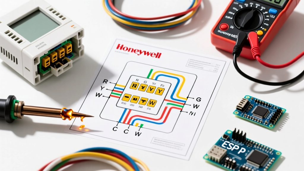
When your HVAC system fails in the middle of a extreme weather snap, guessing which wire controls the compressor or the blower motor is a recipe for a blown control board fuse. Pulling up the correct wiring diagram for thermostat Honeywell models is the single most effective way to isolate electrical faults without wasting time. Whether you are working with a legacy programmable unit or a 2026 smart Wi-Fi model like the Honeywell Home T9 (RTH9585WF), the underlying Class 2 low-voltage architecture remains fundamentally the same.
Honeywell thermostats operate on a 24VAC circuit supplied by the HVAC equipment's step-down transformer. By cross-referencing the physical wires at your baseplate with the manufacturer's schematic, you can systematically eliminate the thermostat, the wiring, or the control board as the point of failure. This guide dives deep into advanced troubleshooting techniques using these diagrams, moving beyond basic installation into real-world diagnostic scenarios.
Safety Warning: Always turn off the main power breaker to your air handler and outdoor condenser before removing the thermostat faceplate or probing terminals. While 24VAC is generally safe from severe shock, accidentally shorting the R (Power) and C (Common) wires can instantly blow the 3A or 5A blade fuse on your furnace control board, turning a simple thermostat fix into a costly board replacement.
Terminal Mapping Matrix: The Honeywell Standard
Before troubleshooting, you must understand what the schematic is telling you. Honeywell uses standard ARI (Air-Conditioning, Heating, and Refrigeration Institute) terminal designations. Below is the diagnostic matrix for the most common terminals found on models like the VisionPro 8000 (TH8320R1003) and the T6 Pro Z-Wave (TH6320ZW2003).
| Terminal | Function | Standard Wire Color | Diagnostic Voltage (Active) |
|---|---|---|---|
| R / Rc / Rh | 24VAC Hot Power | Red | 24-28 VAC to C |
| C | 24VAC Common (Return) | Blue or Black | 0 VAC to C (Reference) |
| W / W1 | Primary Heat (Gas/Oil) | White | 24 VAC to C (when calling) |
| Y / Y1 | Primary Cooling (Compressor) | Yellow | 24 VAC to C (when calling) |
| G | Indoor Blower Fan | Green | 24 VAC to C (when calling) |
| O / B | Heat Pump Reversing Valve | Orange or Dark Blue | 24 VAC (Cooling for O, Heating for B) |
| AUX / E / W2 | Auxiliary / Emergency Heat | White or Brown | 24 VAC to C (when calling) |
Scenario 1: Blank Screen and C-Wire Diagnostics
The most frequent support call for modern smart thermostats is a blank or flashing screen. If your wiring diagram for thermostat Honeywell units indicates a connection at the 'C' terminal, but the screen is dead, you have a power delivery failure. Wi-Fi radios draw continuous current (often 150mA to 300mA), which will quickly drain internal batteries or cause 'power stealing' circuits to fail if the common wire is compromised.
Step-by-Step C-Wire Troubleshooting
- Set your multimeter to VAC (Alternating Current).
- Probe R and C at the baseplate. A healthy transformer will read between 24.0V and 28.0V. If you read below 22.0V, the transformer may be failing, or the 18 AWG solid copper wire run is too long (exceeding 100 feet), causing excessive voltage drop.
- Check for 'Ghost Voltages'. If you removed the C wire and read 12V-15V between R and the bare wire end, this is induced capacitance from wires bundled in the wall. It is not usable current and will not power a smart thermostat.
- Inspect the Control Board. If R to C reads 0V at the thermostat, go to the air handler. Check the 3A automotive-style blade fuse on the control board. A blown fuse here is usually caused by a short between R and C at the thermostat baseplate during a previous installation.
Scenario 2: Heat Pump Blowing Cold Air in Winter
If you have a heat pump system and the air blowing from the registers is cold when the thermostat calls for heat, the issue usually lies in the O/B terminal configuration on your wiring diagram. The reversing valve changes the refrigerant flow direction. Most manufacturers (Carrier, Trane, Lennox) energize the valve in cooling (O terminal). However, Rheem and Ruud energize it in heating (B terminal).
If your physical wiring diagram shows the orange wire on the O/B terminal, but the system behaves incorrectly, the fault is rarely the wire itself. Instead, it is the Installer Setup Number (ISU) inside the Honeywell menu. For the VisionPro 8000, navigate to ISU 200 (System Type) and ensure it is set to Heat Pump. Then, check ISU 205 (Reversing Valve). If you have a Rheem unit and ISU 205 is set to 'O' (Cool), change it to 'B' (Heat). This software mismatch accounts for nearly 40% of 'broken' heat pump installations.
Scenario 3: Auxiliary Heat Strip Failures
During sub-freezing temperatures, heat pumps lose efficiency and rely on electric resistance strips (Aux/E/W2). If your diagram shows a wire at the AUX terminal, but your home isn't reaching the setpoint, the thermostat might not be triggering the strips.
- Verify the Wire Placement: Honeywell uses AUX and E differently. AUX engages automatically during a normal heat pump cycle when the compressor can't keep up. E (Emergency) bypasses the compressor entirely and runs only the strips. If your wire is on E, the strips won't run during normal operation.
- Check the Outdoor Lockout Sensor: Many Honeywell diagrams include an outdoor temperature sensor. If the sensor reads above the economic balance point (e.g., 35°F), the thermostat's logic board will intentionally lock out the AUX strips to save electricity, even if the house is slightly below setpoint.
Isolating the Fault: Baseplate Jumper Tests
When the wiring diagram confirms the wires are on the correct terminals, but the equipment won't turn on, you must determine if the thermostat's internal relay is dead or if the HVAC control board is faulty. You can do this with a simple jumper test using a bent paperclip or a short piece of 18 AWG wire.
The R-to-W Jumper Test
- Remove the thermostat faceplate, leaving the baseplate wired and mounted.
- Turn the main power back on at the breaker.
- Use the paperclip to briefly touch the R terminal and the W terminal simultaneously.
- Result A: If the furnace ignites and the blower starts, your wiring and control board are perfectly fine. The Honeywell thermostat's internal W relay has failed, and the unit (retailing around $140-$180 for a T6 Pro) must be replaced.
- Result B: If nothing happens, the thermostat is not the problem. The fault lies downstream. Check the 24VAC transformer, the limit switches, or the control board's W terminal connection.
Upgrading vs. Repairing: Solving the Missing C-Wire
If your existing wall cavity only has 18/3 or 18/4 thermostat wire and lacks a dedicated C-wire, you cannot reliably run a modern Wi-Fi thermostat. You have two primary solutions:
| Solution | Cost (2026 Estimates) | Pros | Cons |
|---|---|---|---|
| Run New 18/5 or 18/8 Cable | $80 - $150 (Materials + Labor) | Permanent fix; provides dedicated common; supports all future smart home upgrades; complies with NEC Class 2 standards. | Requires fishing wires through finished drywall; highly labor-intensive. |
| Install an Add-a-Wire Kit | $25 - $35 (e.g., Venstar Add-a-Wire) | Uses existing 4-wire setup by multiplexing the G (Fan) and Y (Cooling) signals; installation takes 20 minutes. | Sacrifices independent fan control (G terminal); can cause slight delays in compressor engagement. |
Final Thoughts on Schematic Literacy
Troubleshooting HVAC systems is an exercise in logical elimination. The wiring diagram for thermostat Honeywell units is not just an installation map; it is a diagnostic flowchart. By understanding the 24VAC relationships between R, C, and the call terminals, and by utilizing a multimeter to verify voltage under load, you can confidently diagnose blank screens, reversing valve mismatches, and failed relays without unnecessarily replacing expensive components.
Authoritative References
- Honeywell Home Official Support & Literature Database - For downloading specific ISU manuals and wiring schematics for VisionPro and T-Series models.
- U.S. Department of Energy (Energy Saver) - Guidelines on thermostat placement, low-voltage wiring standards, and energy efficiency impacts of auxiliary heat lockouts.
- NFPA 70: National Electrical Code (NEC) - Article 725 covering Class 1, Class 2, and Class 3 Remote-Control, Signaling, and Power-Limited Circuits.


