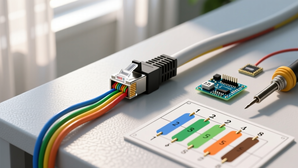

The Reality of 'Cat5' in 2026: What You Are Actually Wiring
When network administrators and low-voltage technicians search for a wiring diagram for Cat5, they are often looking backward in time. True Category 5 cable—rated for 100 MHz and largely obsolete since 2001—has been entirely superseded by Category 5e (Cat5e) and Category 6 (Cat6). However, the physical termination architecture remains identical. The 8P8C (commonly called RJ45) connector and the underlying twisted-pair topology dictate that the wiring diagram for Cat5, Cat5e, and Cat6 are exactly the same.
As an installation planning guide for 2026, this resource will bridge the gap between legacy terminology and modern execution. We will cover the exact pinouts, material selection matrices, National Electrical Code (NEC) routing constraints, and the specific failure modes that plague modern Power over Ethernet (PoE) deployments.
Decoding the Standard Wiring Diagrams: T568A vs. T568B
The ANSI/TIA-568 standard defines two primary wiring schemes for terminating twisted-pair cables. While both diagrams are electrically valid and perform identically in terms of bandwidth, mixing them incorrectly results in a non-functional link. In 2026, T568B remains the dominant commercial standard in the United States, while T568A is heavily favored in residential and government contracts due to its backward compatibility with older USOC telephone wiring.
Pinout Matrix: T568A and T568B
| Pin Number | T568A Color Code | T568B Color Code | Signal / Function (10/100/1000BASE-T) |
|---|---|---|---|
| 1 | White/Green | White/Orange | TX+ (Transmit Data +) |
| 2 | Green | Orange | TX- (Transmit Data -) |
| 3 | White/Orange | White/Green | RX+ (Receive Data +) |
| 4 | Blue | Blue | BI_DD+ (Bi-Directional Data +) |
| 5 | White/Blue | White/Blue | BI_DD- (Bi-Directional Data -) |
| 6 | Orange | Green | RX- (Receive Data -) |
| 7 | White/Brown | White/Brown | BI_DD+ (Bi-Directional Data +) |
| 8 | Brown | Brown | BI_DD- (Bi-Directional Data -) |
Straight-Through vs. Crossover: The Auto-MDIX Factor
Historically, a different wiring diagram for Cat5 was required to create a 'crossover' cable (T568A on one end, T568B on the other) to connect two identical devices, like two PCs or two switches, directly. Stop planning for crossover cables. Since the widespread adoption of Auto-MDIX (Automatic Medium-Dependent Interface Crossover) in Gigabit Ethernet and all modern 2026 networking gear, devices automatically detect and correct the transmit/receive pairs. Always terminate both ends to the exact same standard (preferably T568B for commercial consistency) unless specifically patching a legacy 10BASE-T or 100BASE-TX hub without uplink ports.
Pre-Installation Material & Budget Matrix (2026 Pricing)
Pulling cable is 80% of the labor cost; the cable itself is a minor fraction of the budget. Do not compromise on material quality. Below is a planning matrix for a standard 1,000-foot pull-box of 24 AWG solid copper UTP (Unshielded Twisted Pair).
| Cable Type / Jacket | Use Case | Est. Cost per 1,000ft (2026) | NEC / Fire Rating |
|---|---|---|---|
| Cat5e CMR (Riser) | Standard vertical runs between floors in non-plenum spaces. | $140 - $180 | CMR (UL 1666) |
| Cat5e CMP (Plenum) | Dropped ceilings, HVAC return airspaces, commercial offices. | $220 - $280 | CMP (UL 910) |
| Cat6 CMR (Riser) | New commercial builds requiring 10GBASE-T up to 55 meters. | $180 - $230 | CMR (UL 1666) |
| CCA (Copper Clad Aluminum) | NEVER USE. High resistance, PoE fire hazard, violates TIA. | $60 - $90 | Not UL Listed for Data |
Expert Warning on CCA: Copper Clad Aluminum (CCA) cable is a pervasive counterfeit in the low-voltage market. Because aluminum has higher DC resistance than pure copper, CCA cables overheat when subjected to modern IEEE 802.3bt (PoE++) loads, which can push up to 90W per port. Always verify your spools are 100% bare copper and carry a legitimate UL or ETL mark. For further reading on telecommunications safety standards, refer to the National Fire Protection Association (NFPA) guidelines on communications circuits.
Step-by-Step Blueprinting Your Cable Runs
A successful installation begins long before the first hole is drilled. Follow this planning sequence to ensure your physical layer meets TIA-568 performance benchmarks.
- Map the TR (Telecommunications Room): Identify the central patch panel location. Ensure you have a dedicated 20A circuit for your switches and proper grounding via the TMGB (Telecommunications Main Grounding Busbar).
- Calculate Maximum Run Lengths: The absolute maximum channel length for any Cat5/Cat5e/Cat6 wiring diagram is 100 meters (328 feet). This includes 90 meters of solid horizontal cable and 10 meters of stranded patch cords combined. Always subtract 10% for service loops and routing slack.
- Plan for Separation (NEC Article 800): Data cables must be separated from AC power lines to prevent Electromagnetic Interference (EMI). For standard 120V/240V AC lines, maintain a minimum clearance of 2 inches. If crossing AC lines is unavoidable, do so at a strict 90-degree angle.
- Account for Bend Radius: The minimum bend radius for a 4-pair UTP cable during installation is 4 times the cable's outer diameter (roughly 1 inch). Bending the cable tighter than this alters the twist rate of the internal pairs, destroying the cable's ability to reject crosstalk and causing high Return Loss.
- Determine Pull Tension: Never exceed 25 pounds (110 Newtons) of pulling force. Exceeding this physically stretches the copper conductors and unwinds the internal twists, permanently degrading the cable's Category rating.
Common Failure Modes & Edge Cases
Even with the correct wiring diagram for Cat5, physical installation errors will cause the network to fail certification testing. Watch for these specific edge cases:
1. The 'Split Pair' Error
A split pair occurs when a technician maps the pins correctly for continuity (e.g., Pin 1 to Pin 1, Pin 2 to Pin 2) but uses the wrong color combinations, breaking the twisted-pair geometry. For example, pairing Solid Orange with Solid Blue instead of Solid Orange with White/Orange. A basic $10 continuity tester will show a 'PASS' because the electrical circuit is complete. However, because the signals are no longer traveling on a physically twisted pair, the link will suffer massive Near-End Crosstalk (NEXT) and drop packets under load. Always use a wiremapper that tests for split pairs, or a full certifier.
2. Untwisting Too Much at the Termination
When punching down wires into a 110-block or crimping an RJ45 plug, the internal twists of the pairs must be maintained to within 0.5 inches (13mm) of the termination point. Untwisting the pairs back to the cable jacket to 'make the wires reach' creates an antenna effect, introducing crosstalk and alien crosstalk (AXT) into the channel.
3. PoE Voltage Drop on Long Runs
While the data signal might successfully negotiate a 1Gbps link at 95 meters, the DC voltage for a PoE security camera or Wireless Access Point may drop below the device's operational threshold due to the resistance of 24 AWG copper. If you are deploying 802.3bt Type 3 or Type 4 PoE (60W-90W), plan your runs to stay under 75 meters, or upgrade to 23 AWG Cat6 cable to reduce DC resistance.
Essential Tooling for 2026 Installations
To execute the wiring diagram properly and verify the physical layer, your toolkit must include:
- Pass-Through RJ45 Crimper: Tools like the Klein Tools VDV226-011 allow the conductors to pass completely through the plug before the blade trims them flush. This eliminates the guesswork of wire alignment and ensures all 8 pins make full contact.
- Impact Punch-Down Tool: A 110-style impact tool with a built-in cutter (like the Fluke Networks JackRapid) ensures consistent seating pressure on patch panels and keystone jacks without fraying the copper.
- Cable Certifier: For commercial jobs requiring a warranty, a certifier like the Fluke DSX-5000 or LinkIQ is mandatory. It tests not just continuity, but insertion loss, NEXT, PS-NEXT, and ACR-F against the strict TIA-568 frequency sweeps up to 100 MHz (Cat5e) or 250 MHz (Cat6).
Frequently Asked Questions (FAQ)
Can I use the Cat5 wiring diagram for Cat6a cable?
Yes. The T568A and T568B pinout diagrams are universal across Cat5, Cat5e, Cat6, Cat6a, and Cat8. The physical differences lie in the cable's internal geometry (thicker copper, tighter twists, and often a plastic spline or foil shielding), not the termination pinout. However, you must use Cat6a-rated RJ45 plugs and keystones to accommodate the thicker 23 AWG conductors and maintain the shield's grounding path.
Which standard should I choose for a new commercial office build?
In 2026, best practice dictated by organizations like BICSI and the TIA recommends standardizing on T568B for all new commercial horizontal cabling. T568B matches the vast majority of pre-manufactured patch cords and legacy enterprise infrastructure. Document your choice in the project's site specifications and enforce it across all subcontractors.
Does shielding (STP/FTP) change the wiring diagram?
No. The 8 internal conductors follow the exact same color-coded diagram. However, shielded cables include a drain wire and an outer foil or braid. The drain wire must be properly terminated to the shielded metal body of the RJ45 plug or keystone jack, which in turn grounds to the patch panel rack. If you fail to ground the shield, it acts as a massive antenna, actually worsening EMI susceptibility compared to standard UTP.