
The Blueprint of Climate Control: Understanding HVAC Schematics
For electricians, HVAC technicians, and advanced DIYers, wiring diagrams for HVAC systems are the ultimate diagnostic roadmap. Unlike simple appliance wiring, an air conditioning or heat pump system involves a complex interplay between high-voltage power delivery and low-voltage logic control. Misinterpreting these diagrams can lead to blown control boards, damaged compressors, or severe electrical hazards.
As of 2026, the industry shift toward A2L low-GWP refrigerants and variable-speed ECM (Electronically Commutated Motor) blowers has made HVAC schematics more intricate than ever. Modern units often feature communicating control boards that use DC pulse signals rather than traditional 24V AC analog calls. However, the foundational principles of reading line voltage and 24V control circuits remain the bedrock of HVAC electrical troubleshooting.
The Two Halves of HVAC Wiring: Line vs. Control Voltage
Every standard split-system HVAC schematic is divided into two distinct electrical domains. Understanding where one ends and the other begins is the first step in reading the diagram.
| Feature | Line Voltage Circuit (Power) | Control Voltage Circuit (Logic) |
|---|---|---|
| Typical Voltage | 240V AC (Single Phase) or 120V AC | 24V AC (or 12-15V DC for communicating) |
| Primary Function | Powers compressor, condenser fan, and blower motor | Powers thermostat logic, contactor coils, and relays |
| Overcurrent Protection | Double-pole breaker (30A to 60A) in main panel | 3A or 5A ATC automotive-style blade fuse on control board |
| Wire Gauge/Type | 10 AWG to 6 AWG THHN/THWN or NM-B | 18 AWG multi-conductor thermostat wire (18/5 or 18/8) |
| Danger Level | Lethal shock hazard; arc flash risk | Low shock risk; high risk of component damage if shorted |
Decoding Standard HVAC Schematic Symbols
HVAC wiring diagrams utilize standardized NEMA and IEEE electrical symbols. While manufacturers like Carrier, Trane, and Lennox have slight variations in their schematic layouts, the core symbols remain universal. Here is a breakdown of the most critical components you will encounter:
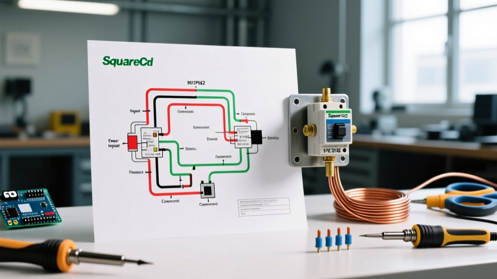
- Contactor (COMP): Represented by a coil symbol (often a circle or rectangle with diagonal lines) paired with switch contacts. The 24V coil energizes the magnetic field, pulling down the high-voltage contacts to send 240V to the compressor.
- Run Capacitor (CAP): Shown as two parallel lines, sometimes with a curved line. Dual run capacitors will have three terminals labeled HERM (Hermetic/Compressor), FAN (Condenser Fan), and C (Common).
- Step-Down Transformer (TRANS): Depicted as two overlapping coils. This is the bridge between line and control voltage, stepping 120V/240V down to 24V AC. Standard sizing is 40VA (Volt-Amperes).
- Pressure Switches (HPS/LPS): Drawn as a standard switch with a diagonal line and a semi-circle underneath. High Pressure Switches (HPS) and Low Pressure Switches (LPS) are wired in series with the contactor coil to break the 24V circuit if refrigerant pressures become unsafe.
- Thermostat Terminals: Standard letter designations include R (24V Hot), C (24V Common), Y (Cooling/Compressor), W (Heating), and G (Indoor Fan).
Step-by-Step Tracing: The 24V Cooling Call Circuit
To truly understand wiring diagrams for HVAC, you must learn to trace a circuit from the power source, through the logic switches, to the load, and back to the common. Let us trace a standard cooling call (Y circuit) on a conventional 240V split-system air conditioner.
1. The Power Source and Transformer
The circuit begins at the 40VA step-down transformer. The secondary side outputs 24V AC. One leg of the secondary connects directly to the R terminal on the thermostat (via the red wire of the 18/5 thermostat cable). The other leg connects to the C (Common) terminal on the control board and the contactor coil.
2. The Logic Path (Series Switches)
When the thermostat calls for cooling, it internally closes the switch between R and Y. The 24V travels down the yellow wire to the outdoor unit. Before reaching the contactor coil, the diagram will show the yellow wire passing through a series of safety switches:
- Low-Pressure Switch (LPS): Ensures the system has adequate refrigerant charge. If the system is empty, this switch remains open, preventing the compressor from running dry.
- High-Pressure Switch (HPS): Protects against blocked condensers or overcharging. If head pressure exceeds safe limits (typically around 600+ PSI for R-410A), the switch opens.
3. The Load and Return
After passing through the safety switches, the 24V reaches one side of the contactor coil. The other side of the coil is wired directly to the 24V Common (C) from the transformer. This completes the circuit, energizing the coil, pulling the high-voltage contacts closed, and starting the compressor and condenser fan.
Pro Troubleshooting Tip: If the thermostat is calling for cool (Y is energized) but the contactor is not pulling in, do not immediately replace the contactor. Use a multimeter to measure the voltage across the coil. If you read 24V AC but the coil does not engage, the coil is mechanically failed or burnt open. If you read 0V AC, you have an open safety switch or a broken thermostat wire in the control circuit.
Common HVAC Wiring Diagram Failure Points
Reading the diagram tells you how the system should work. Field experience tells you where it actually fails. Based on 2026 service data, here are the most frequent electrical failures mapped to their schematic locations:
The Blown 3A Control Fuse
Almost every modern furnace and air handler control board features a 3-amp automotive blade fuse on the 24V secondary side. Why does it blow? According to the schematic, the 24V hot (R) runs out to the thermostat and the outdoor contactor coil. If the 18/5 thermostat wire gets pinched against a sharp sheet metal edge, or if the outdoor contactor coil shorts internally (reading near 0 ohms instead of the normal 10 to 30 ohms), it creates a dead short across the transformer secondary. The transformer will not trip the 30A main breaker; instead, the 3A fuse sacrifices itself to save the 40VA transformer and the control board.
Contactor Coil Resistance Anomalies
A healthy 24V AC contactor coil (such as a standard Supco SC324 or OEM equivalent) should exhibit a resistance between 10 and 30 ohms when measured with a multimeter.
- Reading 'OL' (Open Loop): The internal winding is broken. The contactor will never pull in, even with 24V applied.
- Reading < 2 ohms: The coil is shorted. Applying 24V will instantly blow the 3A control board fuse.
NEC Code Requirements for HVAC Line Voltage
When evaluating the line-voltage portion of wiring diagrams for HVAC, technicians must adhere strictly to the National Electrical Code (NEC), specifically NFPA 70 (NEC) Article 440, which governs Air-Conditioning and Refrigerating Equipment.
Disconnect Sizing and Placement
NEC Article 440.14 requires a disconnecting means to be located within sight from and readily accessible from the air-conditioning equipment. For a standard 3-ton to 4-ton residential condenser drawing a Maximum Circuit Ampacity (MCA) of 20 to 24 amps, a 30A fused or non-fused disconnect is required, fed by 10 AWG copper wire. For 5-ton units or systems with auxiliary electric heat strips, the MCA often exceeds 30A, necessitating 8 AWG wire and a 60A disconnect.
Branch Circuit Sizing
The wiring diagram on the outdoor unit's data plate will list the MCA and the Maximum Overcurrent Protection (MOP). The MCA dictates the wire size (e.g., 10 AWG for up to 30A), while the MOP dictates the breaker size at the main panel. It is entirely common and code-compliant to see a 40A breaker protecting a circuit wired with 10 AWG, provided the MCA on the nameplate is 24A or less and the MOP allows 40A. This exception is unique to HVAC motor circuits under NEC Article 440 to accommodate the high Locked Rotor Amps (LRA) during compressor startup without nuisance tripping.
The 2026 Landscape: Communicating and ECM Systems
While traditional 24V analog diagrams remain prevalent in retrofits and budget installations, modern high-efficiency systems (18+ SEER2) utilize communicating protocols. In these systems, the thermostat and the indoor/outdoor units communicate via a digital data bus, often superimposed over the traditional R and C wires or utilizing dedicated A and B data terminals.
According to the EPA ENERGY STAR program, variable-speed systems drastically reduce energy consumption, but their wiring diagrams look more like computer network schematics than traditional electrical ladders. Troubleshooting these requires proprietary diagnostic tools and a shift from measuring voltage to reading digital fault codes and verifying data bus integrity. However, the line voltage side—feeding the inverter board and the disconnect—remains governed by the same fundamental NEC rules and schematic logic outlined above.
Summary Checklist for HVAC Schematic Analysis
Before opening a panel or touching a wire, run through this diagnostic checklist:
- Verify Power: Confirm 240V at the disconnect and 24V at the transformer secondary.
- Identify the Call: Determine which thermostat terminal (Y, W, G) is currently energized.
- Trace the Safety Loop: Follow the schematic through the LPS, HPS, and float switches to find the open circuit.
- Check the Loads: Measure resistance on contactor coils and relays before applying voltage.
- Respect the NEC: Ensure all line-voltage wiring matches the MCA and MOP specifications on the unit's data plate.
For further reading on maintaining system efficiency and electrical safety, refer to the U.S. Department of Energy's HVAC maintenance guidelines. Mastering HVAC wiring diagrams bridges the gap between basic electrical theory and advanced climate control diagnostics, ensuring safe, efficient, and reliable system operation.