
The Intersection of Electrical and Fire Safety in Commercial Kitchens
Designing and executing a wiring diagram for commercial kitchen hood systems is one of the most heavily scrutinized electrical tasks in the construction industry. Unlike standard commercial ventilation, a Type I commercial kitchen hood (designed for grease and smoke removal) is classified as a life-safety system. The electrical infrastructure must seamlessly integrate with mechanical exhaust, make-up air (MUA) balancing, and wet-chemical fire suppression systems. A single wiring error can result in catastrophic fire spread, negative building pressure causing carbon monoxide back-drafting, or immediate failure during a municipal fire marshal inspection.
In this comprehensive guide, we break down the exact electrical architecture required for modern commercial kitchen hoods, referencing the latest 2026 NEC (National Electrical Code) standards and NFPA 96 compliance requirements. We will focus on the critical interlocks, specific component models, and the precise wiring sequences that separate code-compliant installations from dangerous liabilities.
Core Code Requirements: NEC Article 422, 430, and NFPA 96
Before pulling a single foot of THHN wire, the electrical contractor must understand the overlapping jurisdictions governing kitchen ventilation. The NFPA 96 Standard for Ventilation Control and Fire Protection of Commercial Cooking Operations dictates the mechanical and fire-suppression integration, while the NEC governs the electrical execution.
- NEC Article 422 (Appliances): Governs the disconnecting means for the cooking equipment and the hood itself. Section 422.31(B) requires a lockable disconnect within sight of the hood controller.
- NEC Article 430 (Motors): Dictates the overcurrent protection and wire sizing for the exhaust and MUA blower motors. A 7.5 HP exhaust fan requires specific time-delay fuses or inverse-time breakers to handle starting inrush currents without nuisance tripping.
- NFPA 96 Section 11.3 (Interlocks): Mandates that all fuel and electrical power to cooking equipment under the hood must be automatically shut off when the fire suppression system activates.
Anatomy of a Code-Compliant Wiring Diagram
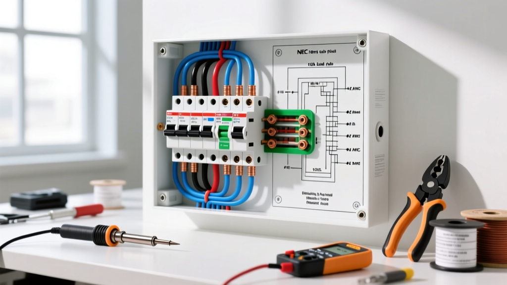
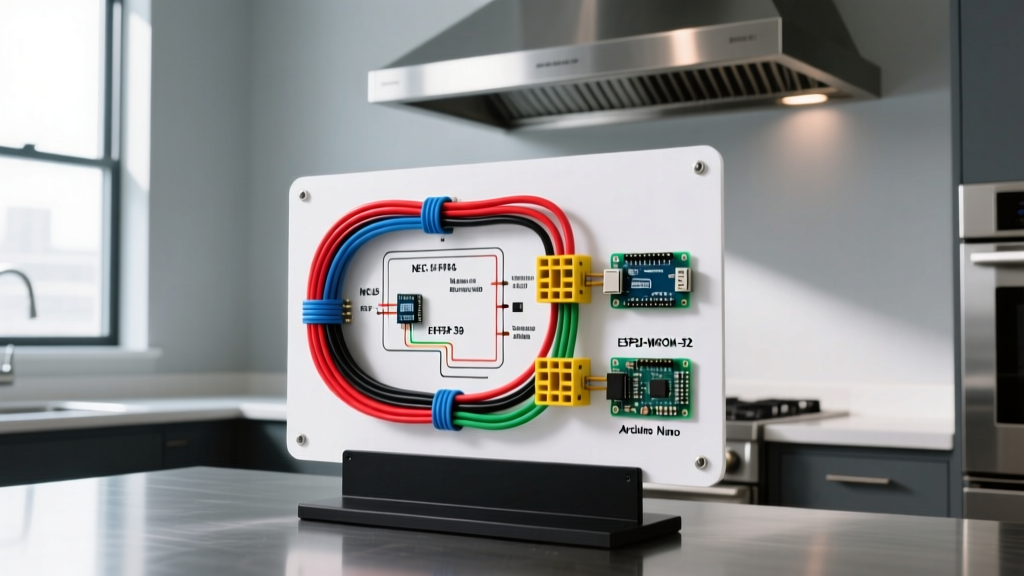
A professional wiring diagram for a commercial kitchen hood is never a single circuit. It is a matrix of high-voltage power feeds and low-voltage control logic. Below is the standard specification matrix for a mid-sized Type I hood utilizing a Greenheck CSP-HP controller and a CaptiveAire Direct Gas-Fired MUA unit.
| System Component | Voltage / Phase | Wire Gauge (THHN) | Breaker / Protection | Conduit Requirement |
|---|---|---|---|---|
| Exhaust Blower Motor (7.5 HP) | 480V / 3-Phase | 8 AWG | 60A HACR Breaker | 1' EMT or Rigid |
| Make-Up Air (MUA) Blower | 208V / 3-Phase | 10 AWG | 40A HACR Breaker | 3/4' EMT |
| Hood LED Lighting Array | 120V / 1-Phase | 12 AWG | 20A Standard Breaker | 1/2' EMT (Sealed) |
| Control Circuit / Interlock | 120V / 1-Phase | 14 AWG | 15A Breaker | 1/2' EMT |
The Ansul Fire Suppression Interlock: The Most Critical Failure Point
The most complex and frequently failed portion of any kitchen hood wiring diagram is the fire suppression interlock. Most commercial kitchens utilize an Ansul R-102 or similar wet-chemical system. When the pneumatic detectors sense a fire (typically at 360°F), the system triggers a mechanical release that simultaneously discharges the chemical agent and actuates a microswitch on the main pull station.
Wiring the Shunt-Trip Breaker
NFPA 96 requires that all gas and electric cooking appliances under the hood lose power upon agent discharge. This is achieved via a shunt-trip breaker installed in the main kitchen appliance panel.
- The Ansul microswitch is wired in series with a 120V control circuit originating from the hood's internal control transformer.
- When the Ansul system trips, the microswitch opens, breaking the 120V circuit.
- This de-energizes the shunt-trip coil on the main appliance breaker (e.g., a Square D PowerPact with a factory-installed shunt-trip module, which typically adds $250 to $400 to the breaker cost).
- The breaker instantly trips, cutting 240V/480V power to ranges, fryers, and flat-top griddles.
Expert Troubleshooting Tip: A common edge-case failure occurs when installers wire the Ansul microswitch directly to the 24V DC coil of a contactor without an isolation relay. The inductive kickback from the contactor coil fries the Ansul microswitch over time. Always use a 120V AC intermediate relay (like an Omron LY2N) to isolate the fire panel from the motor contactors.
Make-Up Air (MUA) Interlocking and Building Pressure
Exhausting 3,000 to 5,000 CFM of air from a kitchen creates massive negative pressure. To compensate, a Make-Up Air unit must supply conditioned air. According to the International Mechanical Code (IMC) and OSHA ventilation standards outlined in OSHA 1910.94, the MUA unit must be electrically interlocked with the exhaust fan.
Proving Airflow with Differential Pressure Switches
Simply wiring the MUA contactor in parallel with the exhaust contactor is a severe code violation. If the exhaust fan belt breaks but the motor continues to draw current, the MUA will continue pumping air into a kitchen that isn't exhausting it, blowing grease vapors into the dining room.
To wire this correctly, integrate a Dwyer Series 1910 differential pressure switch across the exhaust fan plenum.
- Setpoint: Calibrate the switch to close at 0.15' W.C. (Water Column).
- Wiring Sequence: Wire the normally-open (NO) contacts of the Dwyer switch in series with the MUA contactor coil. The MUA fan will only receive power if the exhaust fan is physically moving air and creating the required negative static pressure.
Step-by-Step Wiring Sequence for Greenheck CSP Controllers
Modern commercial hoods often utilize integrated VFD (Variable Frequency Drive) controllers, such as the Greenheck CSP-HP, which modulates fan speed based on hood temperature and optical smoke sensors. Wiring these requires strict adherence to the manufacturer's terminal torque specifications and NEC Chapter 9 conduit fill limits.
1. Main Power and Control Transformer Sizing
Feed 480V 3-phase power into the main hood disconnect. Inside the hood control panel, a step-down transformer converts 480V to 120V for the control logic. Ensure the transformer is rated for a minimum of 250VA. A standard 150VA transformer will saturate and overheat when simultaneously pulling in the MUA contactor, the fire alarm relay, and the VFD cooling fans.
2. Sensor and VFD Integration
Wire the optical smoke sensors using 18 AWG shielded twisted-pair (STP) cable. The shield must be grounded at the controller chassis only to prevent ground loops caused by the high-frequency noise generated by the VFD's PWM (Pulse Width Modulation) output. Terminate the VFD motor leads using crimped ferrules, torqued exactly to 45 in-lbs to prevent arcing under high-vibration conditions.
3. Fire Alarm Control Panel (FACP) Integration
The hood controller must send a signal to the building's main FACP when the Ansul system trips. Wire a dry-contact relay from the hood controller to the FACP's monitor module. Use 16 AWG FPL (Fire Power Limited) cable, routed in a separate conduit from the 120V/480V power lines to satisfy NEC Article 760 separation requirements.
Common Code Violations and Inspection Failures
Even experienced commercial electricians make mistakes when navigating the complexities of kitchen ventilation. Avoid these frequent violations that will result in an immediate failed inspection:
- Shared Neutrals on Multi-Wire Branch Circuits: Running the hood lights and the 120V control circuit on a shared neutral. The harmonic distortion from the VFD can cause the neutral to overheat. Always run dedicated neutrals for hood control circuits.
- Non-Rated Lighting Fixtures: Installing standard commercial LED vapor-tights inside the hood canopy. NEC and NSF require lighting inside a Type I hood to be enclosed in shatterproof, vapor-proof globes specifically listed for grease-laden environments (e.g., Kenall Perma-Safe series). Standard polycarbonate lenses will degrade and melt from the ambient 120°F+ heat and aerosolized grease.
- Missing Lockout/Tagout (LOTO) Provisions: Failing to install a NEMA 3R rated, lockable rotary disconnect switch within 50 feet and within line-of-sight of the exhaust motor, as mandated by NEC 430.102.
- Improper Conduit Sealing: Failing to use EYS conduit seals where the EMT conduit exits the hood canopy. Grease vapor will migrate through the conduit and accumulate inside the junction boxes, creating a severe fire hazard.
Cost Expectations and Material Sourcing in 2026
When estimating a commercial kitchen hood electrical rough-in and trim-out, factor in the premium costs of specialized components. As of 2026, a complete Greenheck CSP-HP hood controller unit ranges from $1,800 to $2,400, depending on VFD sizing. Shunt-trip breakers for the main appliance panel add approximately $350 per pole. Furthermore, NSF-rated shatterproof LED hood lights cost between $250 and $450 per linear foot, significantly higher than standard commercial lighting. Always verify lead times for specialized fire-interlock relays and custom VFD panels, as supply chain variables can still impact project timelines.
Final Verification and Commissioning
Before the fire marshal arrives, perform a simulated trip test. Manually activate the Ansul pull station (with the chemical tanks disconnected or pinned). Verify that the exhaust fan continues to run (NFPA 96 requires the exhaust to remain ON during a fire to pull smoke and chemicals out), the MUA fan shuts down or modulates to a safe baseline, the shunt-trip breaker drops all appliance power, and the FACP registers a supervisory fire signal. Proper execution of the wiring diagram for commercial kitchen hood systems is not just about making the fans spin; it is about engineering a fail-safe environment that protects property and human life.