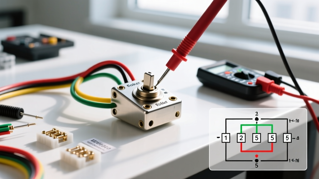

The Critical Role of Diagrams in Switch Troubleshooting
A 5-pin rocker switch is a staple in automotive, marine, and off-grid electrical systems. Typically configured as a Single Pole Double Throw (SPDT) switch with an integrated LED, it offers versatile control over two separate loads or a reversible circuit (like a winch or power window). However, when these switches fail, guessing the wiring layout often leads to short circuits, blown fuses, or melted terminals. As of 2026, high-quality IP68-rated 5-pin switches from brands like DaierTek or Blue Sea Systems cost between $6.50 and $14.00, while generic alternatives sit around $2.50 to $4.00. Regardless of the price point, internal carbon tracking, vibration-induced wiper failure, and thermal runaway remain common failure modes.
To effectively diagnose these issues, you must treat the wiring diagram for 5 pin rocker switch configurations not just as an installation map, but as a diagnostic flowchart. By understanding exactly which internal copper contacts bridge under specific toggle positions, you can isolate faults to the power source, the ground path, the LED circuit, or the load itself.
Decoding the Standard 5-Pin SPDT Pinout Matrix
Before grabbing a multimeter, you must understand the internal topology. The standard 5-pin automotive/marine rocker switch utilizes the following terminal layout. Note that pin numbering is usually molded into the plastic housing near the spade connectors.
| Pin Number | Function | Internal Connection Details |
|---|---|---|
| Pin 1 | LED Ground | Connects to the internal LED resistor path. Must tie to chassis ground. |
| Pin 2 | Output A (Normally Open) | Receives power when switch is toggled UP (Position 1). |
| Pin 3 | Power Input (Common) | The main 12V/24V feed from the battery or fuse block. |
| Pin 4 | Output B (Normally Closed) | Receives power when switch is toggled DOWN (Position 2). |
| Pin 5 | LED Ground / Dummy | Often a secondary ground for dual-LED models, or left unpopulated on single-LED SPDT variants. |
Diagnostic Insight: If your wiring diagram shows Pin 3 as the power input, but your multimeter reads 0V at Pin 2 when toggled UP, the fault lies internally between the common wiper and the NO (Normally Open) contact pad.
Top 3 Field Failures and Diagram-Based Troubleshooting
Fault 1: The 'Ghost Light' (LED Illuminates, Load Remains Dead)
This is the most common complaint in off-road lighting and marine bilge pump circuits. The switch's internal LED lights up, confirming that Pin 3 (Power) and Pin 1 (LED Ground) are functioning. However, the accessory connected to Pin 2 does not activate.
- Step 1: Consult your wiring diagram to verify the load ground. A 5-pin switch diagram only controls the positive switching; if the load's negative terminal lacks a clean chassis ground, the circuit remains open.
- Step 2: Measure voltage at Pin 2 with the switch engaged. If you read 12.6V at Pin 2, but 0V at the load, you have a broken wire or a corroded inline fuse between the switch and the accessory.
- Step 3: If Pin 2 reads 0V while the LED is on, the internal copper wiper has failed to make contact with the Output A pad, often due to carbon buildup from switching high-inrush loads (like compressors) without a relay.
Fault 2: Terminal Melting and Thermal Runaway
If you smell burning plastic or notice the spade connector on Pin 3 has melted the switch housing, you are experiencing thermal runaway. This occurs when current exceeds the switch's rating, or when a loose crimp creates high resistance. According to the NFPA 70 (National Electrical Code), continuous loads must not exceed 80% of a circuit's rated capacity. For a standard 20A-rated 5-pin rocker switch, your continuous load should not exceed 16A.
Expert Tip: Never rely solely on the switch's internal contacts for high-amperage loads. Use the 5-pin switch to trigger a 12V automotive relay, allowing the heavy current to bypass the switch entirely. This extends the switch lifespan from a few months to over a decade.
Fault 3: Intermittent Operation Under Vibration
In UTVs, golf carts, and marine applications, vibration can cause the internal spring-loaded wiper to bounce off the contact pad. If your wiring diagram confirms all external connections are secure and heat-shrunk, the fault is mechanical wear inside the switch housing. There is no repair for this; the switch must be replaced with a higher-grade unit featuring silver-nickel alloy contacts rather than cheap copper-flash alternatives.
Step-by-Step Multimeter Continuity Testing
Using a digital multimeter (DMM) is the fastest way to validate the internal state of the switch without dismantling the dashboard. As outlined in Fluke's official continuity testing guidelines, always isolate the component from power before testing resistance or continuity to prevent blowing your DMM's internal fuse.
- Disconnect Power: Pull the inline fuse or disconnect the negative battery terminal.
- Set DMM: Turn the dial to the continuity setting (soundwave icon) or the lowest Ohms (Ω) range.
- Test OFF Position: Place probes on Pin 3 and Pin 2. The meter should read 'OL' (Open Loop). Repeat for Pin 3 and Pin 4. If you hear a beep in the OFF position, the switch is internally shorted.
- Test Position 1 (UP): Toggle the switch UP. Place probes on Pin 3 and Pin 2. You should hear a continuous beep, and the resistance should read under 0.5Ω. If it reads above 2Ω, the internal contacts are pitted and burning voltage.
- Test Position 2 (DOWN): Toggle the switch DOWN. Place probes on Pin 3 and Pin 4. Verify continuity.
- Test LED Circuit: Set the DMM to the Diode Test mode. Place the red probe on Pin 3 and the black probe on Pin 1. The internal LED should faintly illuminate, and the meter will display the forward voltage drop (usually around 1.8V to 2.2V for standard red/green LEDs).
Wire Sizing and Overcurrent Protection Matrix
A wiring diagram is only as safe as the wire gauge it specifies. Undersized wiring leading to Pin 3 will cause voltage drop, forcing the switch to operate at higher temperatures. Reference the Blue Sea Systems Circuit Protection guidelines for marine and automotive DC wire sizing, which accounts for voltage drop over distance, not just thermal melting points.
| Max Load (Amps) | Recommended Wire Gauge (AWG) | Inline Fuse Size | Typical Application |
|---|---|---|---|
| 5A - 8A | 16 AWG | 10A | LED Light Bars, Horns, USB Hubs |
| 10A - 15A | 14 AWG | 15A or 20A | Bilge Pumps, Cooling Fans, Winch Relays |
| 16A - 20A | 12 AWG | 20A or 25A | Heated Seats, High-Power Inverters, Spotlights |
Environmental Sealing: Beyond the Diagram
When executing your wiring diagram for 5 pin rocker switch installations in harsh environments, the physical connection method matters as much as the electrical topology. Standard vinyl electrical tape will degrade within a single season of UV and moisture exposure. Instead, utilize marine-grade adhesive-lined heat shrink (often rated IP67) on all spade connectors. The internal thermoplastic adhesive melts and flows into the crimp barrel, completely blocking capillary action that causes green copper oxide corrosion. Furthermore, apply a dab of dielectric grease (like NO-OX-ID or standard silicone paste) to the male spade terminals before sliding them onto the switch pins to prevent galvanic corrosion between dissimilar metals.
Summary
Troubleshooting a 5-pin rocker switch requires moving beyond basic visual inspections. By leveraging the wiring diagram to map internal continuity, utilizing a DMM to measure contact resistance, and ensuring your wire gauge aligns with NFPA and ABYC standards, you can permanently resolve ghost lights, melted terminals, and intermittent failures. Always remember: a switch is merely a mechanical bridge. If the bridge is melting, the traffic (current) is too heavy, or the road (wire) is too narrow.