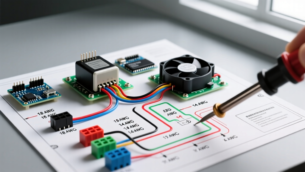

The Critical Role of Electrical Wiring Diagrams in Safety
When approaching any residential, commercial, or industrial installation, electrical wiring diagrams are not merely suggestions; they are the foundational blueprints for life-safety systems. Misinterpreting a schematic or ignoring a wiring diagram's specific routing instructions is a leading cause of arc faults, equipment failure, and electrical fires. As we navigate the widespread adoption of the 2023 and upcoming 2026 National Electrical Code (NEC) cycles, the complexity of modern circuits—particularly those involving AFCI/GFCI protection, solar inverters, and high-amperage EV chargers—demands rigorous diagram literacy.
For DIY enthusiasts and seasoned electricians alike, understanding how to cross-reference electrical wiring diagrams with current NEC articles is the difference between a safe, inspected installation and a hazardous code violation. According to the National Fire Protection Association (NFPA), electrical malfunctions remain a primary cause of structural fires, many of which stem from improper grounding and overcurrent protection miscalculations that a careful review of the manufacturer's wiring diagram would have prevented.
Schematic vs. Pictorial vs. Ladder Diagrams: What the NEC Expects
Not all electrical wiring diagrams serve the same purpose. Before pulling wire or terminating a breaker, you must identify the diagram type provided by the manufacturer and understand its relationship to code compliance.
| Diagram Type | Visual Style | Primary Use Case | NEC Code Relevance |
|---|---|---|---|
| Schematic (Line) | Abstract symbols, straight lines, logical flow | Troubleshooting control circuits, HVAC logic boards | Verifying component isolation and control voltage (Article 430) |
| Pictorial (Wiring) | Physical layout, realistic component images | Appliance installation, panel terminations | Ensuring proper physical spacing and terminal torque (Article 110) |
| Ladder | Vertical power rails, horizontal rungs | Industrial motor controls, PLC integration | Validating overload protection and disconnecting means (Article 430) |
| Single-Line | One line represents three phases, high-level overview | Service entrances, switchgear, solar arrays | Verifying service rating, fault current, and grounding (Article 230) |
4 Critical NEC Violations Prevented by Diagram Analysis
Relying on memory or 'standard practices' instead of the specific electrical wiring diagrams for your equipment frequently leads to severe code violations. Here are four common failures and how diagram literacy prevents them.
1. Shared Neutrals in Multi-Wire Branch Circuits (MWBC)
The Code: NEC Article 210.4(B) requires that all ungrounded conductors of an MWBC be provided with a means to disconnect simultaneously. Furthermore, the neutral must not be shared with unrelated circuits.
The Diagram Fix: When reading panel schedules and branch circuit wiring diagrams, look for the specific grouping identifiers (e.g., 'Circuit 1-3-5 Red/Black/Blue'). If the diagram shows a shared neutral returning to a specific bus bar, installing a standard single-pole breaker instead of a handle-tied or 2-pole breaker violates the simultaneous disconnect rule, creating a severe shock hazard for future maintenance workers.
2. Improper Equipment Grounding and Bonding
The Code: NEC Article 250.142 strictly limits where the grounded (neutral) conductor can be bonded to the equipment grounding conductor.
The Diagram Fix: Appliance wiring diagrams for ranges and dryers historically showed a 3-wire connection (bonding neutral to the chassis). Modern diagrams explicitly mandate a 4-wire NEMA 14-30 or 14-50 configuration. Ignoring the updated diagram and bonding the neutral on the load side of the service disconnect is an immediate fail during inspection and a lethal shock risk.
3. Continuous Load Miscalculations
The Code: NEC Article 210.20(A) dictates that branch circuit overcurrent devices must be rated at no less than 125% of the continuous load (operating for 3 hours or more).
The Diagram Fix: An EV charger wiring diagram might specify a maximum draw of 40 Amps. A novice might install a 40A breaker. However, because EV charging is a continuous load, the diagram's 40A spec requires a 50A breaker (40A x 1.25 = 50A) and wire sized for 50A. Failing to apply the 125% multiplier to the diagram's stated amperage results in nuisance tripping and overheated bus bars.
4. Ignoring Torque Specifications
The Code: NEC 110.14(D) requires that terminations for circuits rated 100A or less be torqued to the manufacturer's specified values using a calibrated tool.
The Diagram Fix: High-end panelboard and transformer wiring diagrams include a torque table (e.g., '35 in-lbs for #8-#2 AWG'). Guessing the tightness leads to loose connections, which the Occupational Safety and Health Administration (OSHA) identifies as a primary precursor to arc flash incidents.
Expert Insight: Never assume terminal tightness by feel. A loose neutral on a 240V/120V split-phase system causes voltage unbalance, potentially sending 200V+ to 120V appliances, destroying HVAC control boards and refrigerators in seconds.
Case Study: Wiring a 240V 50A EV Charger (NEMA 14-50)
Let us apply electrical wiring diagrams to a real-world 2026 scenario: installing a Level 2 Electric Vehicle Supply Equipment (EVSE) hardwired or via a NEMA 14-50 receptacle.
- Read the Manufacturer Schematic: The EVSE diagram specifies a 2-pole 50A breaker, two ungrounded conductors (L1, L2), one grounded conductor (Neutral), and one equipment grounding conductor (EGC).
- Verify Wire Ampacity (NEC 310.15): The diagram recommends 6 AWG copper. However, if you are using NM-B (Romex) cable, 6 AWG is rated for 55A in the 60°C column (NEC 334.80), which is acceptable for a 50A breaker. If you pull individual THHN wires in conduit, you can use the 90°C column, but the termination limits at the breaker (usually 75°C) still govern. 6 AWG THHN copper is perfectly compliant here.
- Map the Receptacle Terminals: The NEMA 14-50 wiring diagram shows the X and Y terminals as Hot (Black/Red), the W terminal as Neutral (White), and the Green terminal as Ground (Bare/Green).
- Apply Torque Specs: The receptacle manufacturer's diagram specifies 75 in-lbs for the terminal screws. Use a calibrated torque screwdriver, such as the CDI Torque 401SMVPH, to secure the connections.
Essential Tools for Diagram Verification and Code Compliance
To ensure your physical installation matches the electrical wiring diagrams and NEC requirements, specific testing and installation tools are mandatory.
- True-RMS Digital Multimeter (e.g., Fluke 117 or Klein Tools MM700): Essential for verifying the absence of voltage before work (NEC 120.6) and checking phase-to-phase (240V) and phase-to-neutral (120V) voltages post-installation to ensure balanced loading.
- Calibrated Torque Screwdriver (e.g., CDI 401SMVPH or Klein 32500 series): Costing between $45 and $120, these tools ensure compliance with NEC 110.14(D), preventing thermal failures at breaker lugs.
- Clamp Meter (e.g., Fluke 325): Used to measure the actual continuous amperage draw on the circuit after installation, verifying it does not exceed 80% of the breaker rating as dictated by the wiring diagram and NEC continuous load rules.
Final Thoughts on Safety and Documentation
Electrical wiring diagrams are legal documents as much as they are technical guides. When an inspector reviews your work, they are comparing your physical installation against the manufacturer's diagram and the NEC. For further reading on grounding, bonding, and complex circuit interpretations, the International Association of Electrical Inspectors (IAEI) provides extensive code-breaking resources and safety bulletins. Always prioritize the manufacturer's specific diagram over generalized internet tutorials, as model-specific variations in internal logic and terminal layouts can drastically alter the required external wiring configuration.