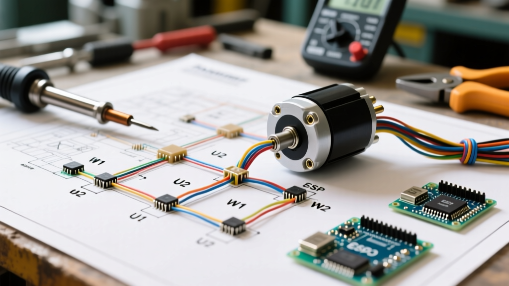

Decoding the 2 Speed Electric Motor Wiring Diagram
Wiring a multi-speed motor requires a precise understanding of internal winding configurations and external control logic. Unlike standard single-speed induction motors, a 2 speed electric motor relies on pole-changing technology or dual independent windings to achieve different RPMs. In commercial HVAC systems, industrial lathes, and heavy-duty pool pumps, the 2 speed electric motor wiring diagram is the critical roadmap for ensuring safe transitions between low and high speeds without causing catastrophic short circuits or winding burnouts.
In this comprehensive reference guide, we break down the exact terminal markings, contactor interlocking requirements, and thermal overload sizing necessary to wire a 2-speed motor correctly in 2026. Whether you are working with a NEMA 56 frame blower motor or an IEC 132M industrial Dahlander motor, the principles below will ensure your installation meets modern electrical codes and operational standards.
The Two Primary 2-Speed Motor Winding Architectures
Before touching a single wire, you must identify which of the two winding architectures your motor utilizes. The wiring diagram on the motor's nameplate will explicitly state one of the following:
1. Dahlander (Pole-Amplitude Modulation / PAM) Winding
The Dahlander connection is the most common and cost-effective method for achieving two speeds from a single winding. By altering the external connection of the stator coils, the number of magnetic poles is doubled or halved. For example, on a 60Hz power supply, a 4-pole configuration yields 1800 RPM (Low Speed), while switching to a 2-pole configuration yields 3600 RPM (High Speed). Dahlander motors are further divided into Variable Torque (fan/pump applications) and Constant Torque (conveyor/hoist applications).
2. Separate Winding (Dual Winding)
Separate winding motors contain two completely independent sets of stator windings housed in the same frame. One winding might be wound for 4 poles (1800 RPM) and the other for 8 poles (900 RPM). These are easier to wire but are physically larger, heavier, and more expensive than Dahlander motors. They are typically reserved for applications requiring highly specific, non-standard speed ratios.
Terminal Block Identification and Power Wiring
Standard IEC and NEMA diagrams use specific alphanumeric designations for the terminal block. Misinterpreting these is the leading cause of immediate motor failure upon startup.
- U1, V1, W1: These are the primary input terminals used for the Low Speed (Delta or Star) configuration.
- U2, V2, W2: These are the secondary terminals used for the High Speed (Double-Star / YY) configuration.
- Shorting Links: In a Dahlander Double-Star (YY) high-speed connection, the U1, V1, and W1 terminals must be physically bridged together with copper shorting links to form the neutral point of the star connection.
Critical Safety Warning: Never apply power to both the low-speed and high-speed contactors simultaneously. Doing so will create a direct phase-to-phase dead short, resulting in an immediate arc flash, destroyed contactors, and potentially a fire. Mechanical and electrical interlocks are strictly mandatory.
Control Circuit Logic and Contactor Interlocking
The physical power wiring is only half the battle. The control circuit diagram dictates how the contactors engage. For a standard Dahlander variable-torque motor, you will need two main power contactors (e.g., Schneider Electric TeSys D LC1D18 for a 10HP 460V motor) and a shorting contactor.
The Interlocking Matrix
| Interlock Type | Component Example | Function in 2-Speed Circuit |
|---|---|---|
| Mechanical Interlock | LAD9R (Schneider) | Physically blocks the high-speed contactor armature from closing if the low-speed contactor is engaged. |
| Electrical Interlock | Normally Closed (NC) Aux Contacts | Breaks the coil circuit of Contactor 2 if Contactor 1 is energized. Prevents coil burnout. |
| Transition Timer | Eaton ETR14 (Off-Delay) | Introduces a 0.5s to 1.0s dead-time when switching from Low to High to allow back-EMF to dissipate. |
Thermal Overload Protection: The Dual-Relay Requirement
A massive point of failure in DIY and novice installations is attempting to use a single thermal overload relay for a 2-speed motor. Because the Full Load Amps (FLA) change drastically between speeds, a single relay cannot protect both windings accurately.
The 2026 Standard Practice: You must install two separate thermal overload relays, one in the power path of the low-speed contactor and one in the power path of the high-speed contactor. For instance, if your motor nameplate reads 'Low Speed FLA: 4.2A / High Speed FLA: 6.8A', you will set one TeSys LRD10 relay to 4.2A and a second LRD12 relay to 6.8A. Both overload NC (95-96) contacts must be wired in series within the main control circuit stop loop so that a trip on either speed drops out the entire system.
Step-by-Step Wiring Procedure (Dahlander Variable Torque)
- Verify Power & Lockout: Confirm zero energy state with a CAT III multimeter. Lock out the main disconnect.
- Wire the Control Circuit: Route your 120V AC or 24V DC control wires. Install the electrical interlocks (NC auxiliary contacts) in series with the opposing contactor coils. Wire the off-delay timer to ensure a minimum 500ms break-before-make transition.
- Install Overload Relays: Mount the two thermal overloads directly beneath their respective contactors. Set the dials to the exact FLA printed on the motor nameplate.
- Terminate Power Wires: Using appropriately sized wire (e.g., 12 AWG THHN copper for circuits up to 20A), connect L1, L2, L3 to the low-speed contactor, and run a separate feed to the high-speed contactor. Connect the output of the low-speed contactor to U1, V1, W1. Connect the output of the high-speed contactor to U2, V2, W2.
- Install Shorting Links: Place the factory-provided copper links across U1, V1, and W1 to enable the Double-Star (YY) high-speed neutral point.
- Test Rotation & Transition: Bump the low-speed starter. Check shaft rotation. Bump the high-speed starter. Verify the timer delay prevents contactor chatter during the transition.
Common Failure Modes and Troubleshooting
Even with a perfect 2 speed electric motor wiring diagram, field conditions can introduce faults. According to motor diagnostics experts, here are the most frequent edge cases:
- Motor Hums but Won't Start on High Speed: This almost always indicates a missing or loose shorting link on U1, V1, W1. Without the neutral bridge, the YY winding cannot form, resulting in single-phasing and severe magnetic imbalance. Check the links with a micro-ohmmeter.
- Breaker Trips Instantly on Speed Transition: The transition timer is set too short, or is missing entirely. When switching from 1800 RPM to 3600 RPM, the motor acts as an induction generator for a fraction of a second. If the high-speed contactor closes before the back-EMF collapses, the resulting out-of-phase current spike will trip the magnetic instant trip on the main breaker. Increase timer delay to 0.8 seconds.
- Overheating on Low Speed: Often caused by wiring a 'Constant Torque' Dahlander motor using a 'Variable Torque' diagram. Constant torque applications (like winches) require a specific Star-to-Double-Star wiring sequence. Re-verify the nameplate schematic against the physical connections.
Authoritative References and Standards
When designing or auditing 2-speed motor control panels, always refer to established industry standards to ensure compliance with the National Electrical Code (NEC) and international safety norms. For detailed specifications on motor performance, winding tolerances, and temperature rise limits, consult the NEMA MG-1 Motors and Generators Standard. For field diagnostics, vibration analysis, and winding resistance testing procedures, the Fluke Motor Troubleshooting Guide provides excellent baseline metrics. Finally, for exact torque specifications on terminal blocks and specific Dahlander connection schematics, refer to the Schneider Electric TeSys Contactors and Motor Starters documentation, which remains the industry benchmark for reliable interlocking hardware.