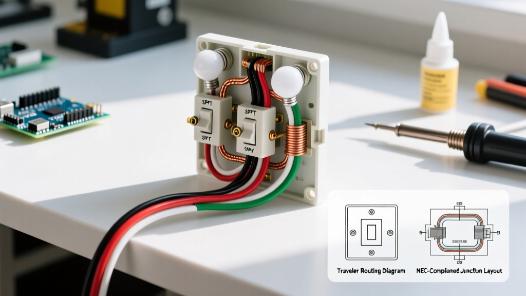

The Motor Control Approach to Residential Lighting
Industrial electricians and motor control technicians often view residential lighting circuits through the lens of logic gates and relay schematics. When you strip away the aesthetic faceplates, a standard 3-way switch is mechanically identical to the Single-Pole Double-Throw (SPDT) selector switches used in motor forward/reverse control circuits. Understanding the wiring diagram for a 3 way switch with 2 lights becomes significantly easier when you treat the switches as SPDT logic routers and the light fixtures as parallel motor loads.
In motor controls, we trace current from the line-side disconnect, through the interposing relays, down the traveler conductors, and into the load-side contactors. We will apply this exact same rigorous troubleshooting and wiring methodology to this residential lighting scenario. By mapping the circuit states (Logic 1 for ON, Logic 0 for OFF), you can eliminate the guesswork that plagues standard DIY tutorials and achieve a flawless, code-compliant installation.
Circuit Topology: Power at Switch 1, Loads at the End
There are multiple ways to route a multi-light 3-way circuit, but the most robust and easily troubleshooted topology—especially for future smart-switch upgrades—is bringing the main power feed into the first switch box, running travelers to the second switch box, and daisy-chaining the two light fixtures at the end of the run. This mimics a standard motor control circuit where the logic switches are grouped before the final load distribution.
Component & Wire Gauge Specifications
Before pulling wire, verify your components. Modern LED lighting introduces unique capacitive and inductive reactance issues that older incandescent circuits didn't face. Below is the recommended Bill of Materials (BOM) for a 15-Amp, 120V circuit.
| Component | Specification / Model | Technical Notes |
|---|---|---|
| Switches | Leviton Decora 5603 (15A) or Lutron Maestro MACL-LFQH | SPDT 3-Way. Lutron model includes advanced LED anti-flicker circuitry. |
| Conductors | 14/3 NM-B (Romex) & 14/2 NM-B | 14 AWG is standard for 15A lighting. Use 12 AWG if the run exceeds 75 feet to mitigate voltage drop. |
| Wire Connectors | Ideal Wire-Nut 341 (Blue) or WAGO 221 Lever | WAGO connectors are highly recommended for multi-wire traveler splices to ensure high-vibration continuity. |
| Light Fixtures | Integrated LED Recessed (e.g., Halo HLB6) | Ensure drivers are rated for 60Hz triac dimming if using the Lutron Maestro. |
Step-by-Step Execution: Tracing the Current Path
Let's trace the current path using motor-control logic. We will define the black wire as the primary Line/Hot, the white as the Neutral return, and the red/black pair as the Traveler logic bus.
- Line-Side Feed (Switch Box 1): The 14/2 power feed enters Box 1. Connect the bare ground to the box and the switch ground screw. Splice the white neutral wires together with a WAGO connector and push them to the back of the box. Do not connect the neutral to the switch. Connect the black (hot) line wire to the Common Terminal (usually the dark-colored screw) on Switch 1.
- The Traveler Logic Bus (Between Boxes): Run 14/3 NM-B from Box 1 to Box 2. Connect the red and black wires of this cable to the two brass Traveler Terminals on Switch 1. Connect the other end of these red and black wires to the brass Traveler Terminals on Switch 2. The white wire in this 14/3 cable will serve as your neutral continuation; splice it with the incoming neutral in Box 1 and the outgoing neutral in Box 2.
- Load-Side Routing (Switch Box 2): The white neutral from the 14/3 cable splices to the white neutral of the 14/2 cable heading to Light 1. Connect the Common Terminal on Switch 2 to the black wire of the 14/2 cable heading to Light 1. This black wire is now your 'Switched Hot'.
- Parallel Load Distribution (Light 1 to Light 2): At the first light fixture junction box, connect the incoming Switched Hot (black) to the black lead of Light 1. Splice a new 14/2 black wire to this same node and run it to Light 2. Repeat this parallel splicing for the white neutral wires and bare ground wires. This ensures both lights operate in parallel; if one LED driver fails open, the other remains operational.
Motor Control Pro-Tip: Always tag your traveler wires with red electrical tape at both ends. In complex junction boxes, treating travelers as a distinct 'logic bus' prevents catastrophic miswiring when upgrading to smart relays later.
NEC 2026 Compliance: The Neutral Wire Mandate
One of the most critical updates in the NFPA 70 National Electrical Code (NEC) that carries heavily into the 2026 adoption cycle is Article 404.2(C). This article mandates that a neutral conductor must be present at all switch locations, even if the current mechanical SPDT switch does not require it.
Why? The explosion of IoT motor controls, smart lighting relays, and occupancy sensors requires a continuous 120V standby power source. If you wire a 3-way circuit using the old 'dead-end traveler' method (where the neutral is only at the light fixture and the switch only interrupts the hot), you will fail inspection in 2026. By routing the 14/3 cable as described in Step 2, you utilize the white conductor to pass the neutral through both switch boxes, ensuring full compliance and future-proofing the circuit for Wi-Fi or Zigbee smart switches.
Troubleshooting Matrix: Finding the Fault
When a 3-way circuit fails, DIYers often swap parts blindly. As a technician, you should use a digital multimeter (like the Fluke 117) to test logic states. Below is a troubleshooting matrix based on common SPDT failure modes.
| Symptom | Probable Logic Fault | Multimeter Test & Resolution |
|---|---|---|
| Lights only turn ON when SW1 is UP, regardless of SW2. | Open circuit on one traveler; SW2 is isolated from the logic bus. | Test continuity between SW1 brass screws and SW2 brass screws. Replace the 14/3 cable or re-terminate WAGO connections. |
| Lights flicker or glow faintly when OFF. | Induced voltage on travelers or incompatible LED driver. | Measure AC voltage across the light fixture when off. If >5V, install a Lutron LUT-MLC (Minimum Load Capacitor) across the first fixture. |
| Breaker trips instantly upon toggling SW2. | Ground fault or short between Switched Hot and Ground at Light 1. | Isolate Light 1. Perform an insulation resistance test (Megger) on the load-side 14/2 cable to identify crushed insulation in the junction box. |
Frequently Asked Questions
Can I use 12 AWG wire for this 15-Amp lighting circuit?
Yes. While 14 AWG is the minimum code requirement for a 15-Amp breaker, using 12 AWG (rated for 20 Amps) is highly recommended by experts at Mike Holt Enterprises for long residential runs. It reduces voltage drop, which is critical for ensuring the internal LED drivers receive a clean 120V sine wave, preventing premature capacitor degradation.
Do I need a special switch for LED lights?
Standard mechanical SPDT switches (like the Leviton 5603) work perfectly with LEDs because they simply make or break the physical circuit. However, if you are installing a dimming 3-way switch, you must use an LED-rated model (like the Lutron Maestro) to handle the low-wattage capacitive loads without causing strobing or ghosting.
What if my existing switch box doesn't have a neutral wire?
If you are retrofitting an older home and lack a neutral at the switch box, you cannot legally install a hardwired smart switch under NEC 2026 guidelines without pulling new cable. The alternative is to use a smart switch system that utilizes wireless RF communication between the master switch and a battery-powered or line-powered remote switch, bypassing the need for physical traveler wires entirely. Consult Leviton Technical Support for specific RF-compatible 3-way kits.