
The Evolution of Harley Davidson Circuit Protection
When you pull up a wiring diagram for Harley Davidson motorcycles, the power distribution section looks vastly different depending on the model year. Historically, Harley-Davidson relied on simple thermal circuit breakers and glass fuses. Today, the transition to CAN bus (Controller Area Network) architecture and solid-state Power Distribution Modules (PDM) has completely changed how we diagnose and upgrade electrical panels.
Understanding these shifts is critical. A diagnostic approach that works on a 2010 Road Glide will leave you stranded if applied to a 2024 Street Glide 117. Below, we break down the exact hardware, schematic symbols, and troubleshooting protocols required for modern Harley fuse panels.
Circuit Protection Hardware by Generation
| Model Years | Primary Breaker Type | Secondary Fuses | Architecture & Key Features |
|---|---|---|---|
| 1999 – 2013 (Touring) | 30A Thermal Auto-Reset Breaker | Glass (SFE) & early ATO Blade | Analog. Breaker mounted near starter. Susceptible to heat fatigue. |
| 2014 – 2023 (Touring/Softail) | 40A / 50A Maxi Blade Fuse | ATO/ATC Blade (15A, 20A) | CAN bus introduced. Centralized fuse block in left saddlebag/fairing. |
| 2024 – 2026 (New Touring/Pan Am) | Solid-State eFuses (BCM) | Software-Resettable & Maxi | Body Control Module (BCM) manages load. No physical fuses for accessories. |
Decoding the Wiring Diagram for Harley Davidson Power Distribution
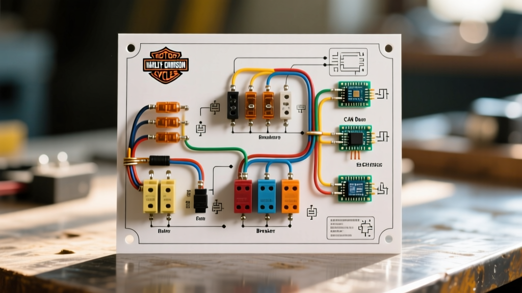
Reading the schematic requires knowing the specific symbols Harley-Davidson uses for its power distribution. Unlike standard automotive diagrams, Harley integrates the SAE J1128 low-tension cable standards with proprietary CAN bus data lines.
Key Schematic Symbols and Wire Colors
- Main Power (Red / Red-White): Direct battery feed. On 2014+ models, this routes through a 40A Maxi fuse before hitting the main ignition relay.
- Ignition Switched (Orange / Orange-White): Hot only when the key is in the 'ON' position. Powers the dash, ECM, and fuel pump.
- CAN High (Gray) & CAN Low (Gray-Black): Twisted pair data lines. Never tap into these for accessory power. A voltage spike here will crash the entire network.
- Ground (Black / Black-White): Routes to the central ground distribution block, usually located under the seat or behind the side cover.
- Accessory (Red-Green or dedicated Deutsch DT): Switched power specifically isolated for add-ons like heated grips or auxiliary lights.
Expert Warning: On 2018-2023 Softail models, the fuse block is located under the seat, directly above the battery. Moisture ingress from riding in heavy rain without the seat properly sealed is the #1 cause of green corrosion on the ATO blade terminals. Always apply dielectric grease (like Permatex 22058) to these terminals during annual service.
Step-by-Step Troubleshooting: Dead Dash & No Crank
When a modern Harley loses all power, amateurs immediately start swapping fuses. As a professional, you should follow a voltage-drop diagnostic flow. According to Littelfuse automotive blade standards, a visual inspection of a blade fuse is not enough; micro-fractures can cause intermittent resistance that triggers CAN bus overcurrent codes without visibly blowing the element.
- Test the Main Maxi Fuse (2014-2023): Locate the 40A Maxi fuse in the primary fuse block. Use a multimeter to check for voltage on both sides of the fuse with the battery connected. If you have 12.6V on the line side and 0V on the load side, the fuse is blown. Do not just replace it. A blown main Maxi indicates a dead short to ground, often caused by chafed wiring near the steering head or a failed voltage regulator.
- Check the Ignition Relay: If the main fuse has power on both sides, locate the ignition relay in the secondary fuse block. Listen for the audible 'click' when turning the key. If no click, test the relay coil ground (usually a Black wire) for continuity to the frame.
- Inspect the CAN Bus Fuses: Modern Harleys use dedicated 15A ATO fuses for the ECM and Body Control Module (BCM). If these blow, the dash will remain completely black because the modules cannot wake up to send data.
- 2024+ BCM eFuse Reset: If you are working on a 2024 or newer Street Glide or Road Glide, physical fuses for accessories do not exist. The BCM uses solid-state eFuses. If an accessory shorts, the BCM throws a Diagnostic Trouble Code (DTC) and shuts off the circuit. You must clear the code via the Harley-Davidson Digital Technician II (DT2) tool or a high-end aftermarket scanner like the Techno Research Centaur to reset the breaker.
Adding Accessories: Tapping the Fuse Panel Safely
One of the most common reasons riders search for a wiring diagram for Harley Davidson panels is to install auxiliary lighting, heated gear, or audio amplifiers. Tapping the wrong circuit on a CAN bus bike will result in 'Accessory Overcurrent' errors and limp-mode engine operation.
The Deutsch DT Accessory Connector
On 2014 and newer Touring models, Harley provides a dedicated accessory connector (usually a 4-pin Deutsch DT plug) located inside the fairing or under the seat. This connector provides:
- Pin 1 (Red/Green): Switched 12V (Ignition controlled).
- Pin 2 (Black): Dedicated Ground.
- Pin 3 (Gray): CAN High (Data only).
- Pin 4 (Gray/Black): CAN Low (Data only).
Crucial Limitation: The switched 12V pin on the OEM harness is typically protected by a 5A to 10A circuit breaker inside the BCM. If you are installing a 60W LED light bar (drawing ~5A) plus a 4A heated vest, you will exceed the limit and trip the BCM.
Proper Heavy-Load Accessory Wiring
For loads exceeding 5 amps, you must bypass the OEM fuse panel and build a secondary distribution block. Here is the exact specification for a safe, high-current auxiliary panel:
| Component | Specification | Estimated Cost (2026) |
|---|---|---|
| Power Feed Wire | 10 AWG Marine-Grade Tinned Copper | $1.50 / foot |
| Main Inline Fuse | 30A ANL Fuse with Marine Holder | $18.00 |
| Auxiliary Fuse Block | Blue Sea Systems ST Blade (6-Circuit) | $45.00 - $55.00 |
| Trigger Relay | 12V 40A Bosch-style Relay (ISO) | $12.00 |
Installation Steps: Run the 10 AWG power feed directly from the starter positive stud (not the battery terminal, to avoid crowding). Install the 30A ANL fuse within 6 inches of the stud. Route the wire to the Blue Sea fuse block. Use the OEM Deutsch DT switched 12V wire only to trigger the 85/86 coil pins on the Bosch relay. This ensures your heavy loads draw directly from the alternator/battery while still turning on and off with the ignition key.
Frequently Asked Questions
Why does my 2019 Road King keep blowing the 15A 'Accessories' fuse when I use heated grips?
Harley-Davidson's OEM heated grips draw approximately 3.5 to 4 amps on the 'High' setting. If you have also plugged in a heated jacket liner (drawing 6+ amps) into the same accessory circuit, your combined draw exceeds the 10A physical limit of that specific fuse block circuit. You must wire the jacket liner to a separate relay-triggered auxiliary fuse block as outlined above.
Can I replace a blown 30A thermal breaker on my 2011 Street Glide with a standard blade fuse?
No. The 30A thermal breakers used on older Harleys are designed to handle the high inrush current of the starter motor solenoid and the initial spike of the voltage regulator. A standard 30A ATO blade fuse will blow instantly under the inrush load of the starter. Always replace with an exact OEM-spec auto-reset thermal breaker (Harley part number 70300-99A or equivalent).
How do I check for electrical recalls on my specific VIN?
Electrical fires and short circuits have been the subject of several NHTSA investigations over the years. Before modifying your fuse panel, always run your VIN through the National Highway Traffic Safety Administration (NHTSA) database to ensure your bike hasn't been flagged for a factory wiring harness chafing recall or a defective OEM voltage regulator ground.