
The Critical Junction: Utility Grid to Home Panel
The service entrance is the most critical electrical junction in any home. Understanding a residential electric meter box wiring diagram is essential for electricians, inspectors, and advanced DIYers overseeing a service upgrade. This enclosure represents the exact handoff point between the utility company's grid and the homeowner's private electrical system. As of 2026, with the widespread adoption of the NEC 2023 code cycle across most U.S. jurisdictions, meter box configurations have evolved significantly to incorporate exterior disconnects and advanced grounding mandates.
Safety Warning: The line-side terminals in a meter socket remain energized even when the main breaker is turned off. Working on the line side requires the utility company to physically disconnect the drop or lateral feed. Always consult OSHA electrical safety guidelines and local utility protocols before removing a meter socket cover.
Anatomy of a Modern 200A Meter Socket Enclosure
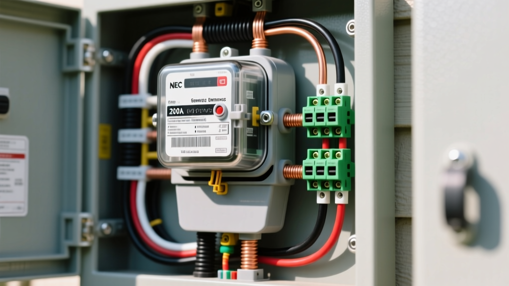
Before tracing the wiring diagram, you must understand the physical components inside the enclosure. A standard 200A residential meter socket (such as the widely used Milbank M9153-XL ringless socket or the Square D HOM812150NS meter-main combo) contains several critical nodes:
- Line-Side Lugs (Top): These terminate the utility's service drop or underground lateral conductors. They are always live when the utility is connected.
- Load-Side Lugs (Bottom): These terminate the Service Entrance (SE) cable that feeds the home's main distribution panel.
- Neutral / Ground Bus: A central or side-mounted lug block where the utility neutral, the home's neutral, and the grounding electrode conductor (GEC) meet.
- Meter Jaws: Spring-loaded copper contacts that grip the watt-hour meter. Modern 200A sockets use heavy-duty 4-jaw or 5-jaw (continuous neutral) configurations.
- Hub or Knockouts: Entry points for conduit (top/side) or direct SE cable entry (bottom).
Decoding the Residential Electric Meter Box Wiring Diagram
When you look at a manufacturer's wiring diagram for a meter socket, the flow of electricity is strictly top-down or side-to-side depending on the hub configuration. Here is how the circuit paths are mapped:
1. The Line-Side Path (Utility Feed)
The utility provides three conductors for a standard 120/240V single-phase split system: two hot legs (L1 and L2) and one neutral (N). According to the U.S. Department of Energy, these conductors land on the top line-side lugs. The diagram will show L1 and L2 routing directly into the upper meter jaws, while the neutral routes to the neutral busbar.
2. The Load-Side Path (House Feed)
The load-side conductors exit the lower meter jaws and land on the bottom load-side lugs. From here, they travel through the Service Entrance (SE) cable directly into the main breaker panel. In a 'Meter-Main' combo unit (required by modern codes in many areas), the load-side lugs route directly into an integrated 200A main breaker before exiting to the interior subpanel.
Service Entrance Conductor Sizing for 2026 Upgrades
Selecting the correct wire gauge is dictated by NEC Article 230 and the specific ampacity tables. In 2026, aluminum XHHW-2 or SER (Service Entrance Round) cable remains the industry standard for residential 200A services due to copper pricing volatility (copper 2/0 AWG can exceed $12/ft, whereas 4/0 AL SER hovers around $4.50/ft).
| Service Ampacity | Copper (THHN in Conduit) | Aluminum (XHHW-2 / SER) | Typical Application |
|---|---|---|---|
| 100 Amp | #3 AWG | #1 AWG | Older homes, small additions |
| 150 Amp | #1 AWG | #2/0 AWG | Standard modern builds (pre-2020) |
| 200 Amp | #2/0 AWG | #4/0 AWG | Current standard, EV charger ready |
| 320 Amp (400A Class) | #350 kcmil | #600 kcmil | Large estates, dual 200A panels |
The NEC 230.85 Exterior Disconnect Mandate
If you are studying a residential electric meter box wiring diagram for a new build or a major upgrade in 2026, you must account for NEC 230.85. This code requires an exterior emergency disconnect for one- and two-family dwellings.
This means a standalone meter socket (like the basic Milbank M9153) is no longer compliant on its own in most jurisdictions unless the utility provides a lockable, exterior service disconnect. The standard solution is installing a Meter-Main combination unit (e.g., Eaton MB816B200BTS). The wiring diagram for a Meter-Main differs from a standard socket: the load-side lugs wire directly to the main breaker's line terminals, and the breaker's load terminals then feed the interior panel via a 4-wire feeder.
Termination and Torque Specifications
A wiring diagram only shows you where wires go; it does not show you how to terminate them. NEC 110.14(D) mandates that all terminations be torqued to the manufacturer's specifications using a calibrated tool. Failure to do so is the leading cause of meter box fires.
- Strip Length: Strip exactly 1.5 inches of insulation from 4/0 AWG aluminum SE cable. Do not nick the outer strands.
- Anti-Oxidant Compound: Apply a liberal amount of Noalox or equivalent antioxidant paste to the exposed aluminum strands before inserting them into the lug barrel. Aluminum oxidizes rapidly, creating a high-resistance layer that generates heat.
- Torque Application: For a standard 200A Milbank socket with 4/0 aluminum, the manufacturer specifies 250 inch-pounds (approx. 20.8 ft-lbs). Use a calibrated torque screwdriver (like the CDI 1002MFRMH) to achieve this exact value.
Grounding and Bonding (NEC Article 250)
The neutral busbar in the meter socket is the primary bonding point for the service. According to NFPA electrical safety standards, the following must be bonded at this exact location:
- Utility Neutral: The grounded conductor from the transformer.
- House Neutral: The grounded conductor of the SE cable.
- Grounding Electrode Conductor (GEC): A #4 AWG bare copper wire routing to two 5/8-inch x 8-foot ground rods (spaced 6 feet apart) or a UFER (concrete-encased) ground.
- Enclosure Bonding: The metal socket enclosure itself must be bonded to the neutral bus via a green bonding screw or a dedicated bonding jumper.
Troubleshooting Common Meter Box Failures
Even with a perfect initial installation, environmental factors and thermal cycling can degrade connections over time. Use a thermal imaging camera (such as the FLIR E8-XT) to scan the meter box under heavy load (e.g., when the HVAC and EV charger are running simultaneously).
Failure Mode 1: Harmonic Heating on the Neutral Lug
If the neutral lug shows a temperature delta of >15°F compared to the hot legs, the connection is loose. Because modern homes use switch-mode power supplies (LEDs, computers, variable frequency drives in HVAC), triplen harmonics add up on the neutral conductor. A loose neutral will overheat rapidly under these conditions.
Failure Mode 2: Melted Meter Jaws
If the plastic meter socket base shows melting around the lower jaws, the meter blades are not making full contact. This is often caused by using a 100A-rated meter (which has shorter, thinner blades) in a 200A socket. Always ensure the meter form number (e.g., Form 2S) and ampacity rating match the socket's jaw depth and spring tension.
Frequently Asked Questions
Can I wire my own electric meter box?
While homeowners can physically mount the enclosure and pull the SE cable in some municipalities, the actual termination of the line-side conductors and the final energization must be performed or inspected by the utility company and a licensed electrician. The utility owns the line-side lugs and will not energize a DIY-terminated socket without an inspector's green tag.
What is the difference between a ring-type and ringless meter socket?
Ring-type sockets use a metal securing ring that the utility seals with a lead or plastic tamper tag. Ringless sockets (the modern standard for 200A residential) use a hinged, lockable cover that seals directly over the meter face, making meter swaps easier for utility technicians without breaking a physical seal ring.
Does the meter box need its own ground rod?
The meter box does not need a separate ground rod if the main panel is immediately adjacent (within 5 feet) and shares the same grounding electrode system. However, the Grounding Electrode Conductor (GEC) must pass through or terminate in the meter socket's neutral bus to bond the enclosure to earth ground, per NEC 250.24(A)(1).