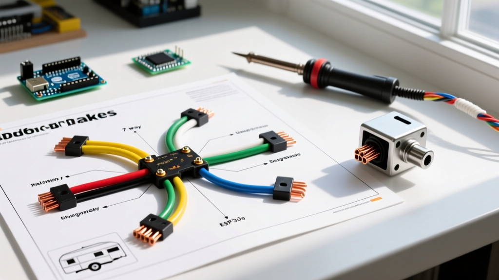

Decoding the 7-Way RV Blade: Your Baseline Diagram
Upgrading from a standard 4-pin flat connector to a 7-way RV blade is mandatory when towing heavy loads requiring electric brakes. While a basic 4-pin setup only handles taillights, brake lights, and turn signals, a 7-way connector introduces dedicated circuits for electric brake control, 12V auxiliary power, and reverse lights. Understanding your trailer wiring diagram with electric brakes is the first step in diagnosing voltage drops, PWM signal failures, and ground bounce issues.
Below is the industry-standard SAE J286 pinout matrix for the 7-way RV blade connector (viewed from the wiring side of the plug). This is the foundational reference you will use for all multimeter testing.
| Pin Position | Function | Standard Wire Color | Recommended Gauge | Circuit Type |
|---|---|---|---|---|
| Pin 1 (Top Center) | Ground / Chassis | White | 8 AWG | DC Return Path |
| Pin 2 (Top Right) | Electric Brakes | Blue | 10 AWG | PWM Signal (Up to 12A) |
| Pin 3 (Bottom Right) | Tail / Running Lights | Brown | 12 AWG | Constant 12V DC |
| Pin 4 (Center Right) | 12V Auxiliary / Charge | Black | 10 AWG | Constant 12V DC |
| Pin 5 (Bottom Left) | Right Turn / Stop | Green | 12 AWG | Switched 12V DC |
| Pin 6 (Center Left) | Left Turn / Stop | Yellow | 12 AWG | Switched 12V DC |
| Pin 7 (Top Left) | Reverse Lights / Aux | Purple | 12 AWG | Switched 12V DC |
The Heart of the System: Brake Controller Integration
Electric trailer brakes do not run on simple constant voltage. Modern proportional brake controllers, such as the Tekonsha Prodigy P3 (retailing around $165 in 2026) or the Redarc Tow-Pro Elite V3 (approximately $225), utilize Pulse Width Modulation (PWM) to send a variable duty-cycle signal down the Blue wire (Pin 2). This allows the brakes to apply smoothly rather than locking up instantly.
Expert Insight: Never use a standard incandescent test light to diagnose the Blue electric brake wire. Test lights cannot accurately read PWM signals and will often display a dim, flickering glow that mimics a bad connection. Always use a digital multimeter (DMM) set to DC Voltage or a dedicated PWM diagnostic tool.
Brake Controller Pigtail Wiring
The brake controller itself requires a 4-wire pigtail connection under the tow vehicle's dashboard:
- White: Ground (Connect to clean, bare metal chassis or heavy ground busbar).
- Black: 12V Power Input (Connect to battery via a 20A or 30A inline circuit breaker).
- Red: Stoplight Switch Input (Taps into the cold side of the vehicle's brake pedal switch).
- Blue: Brake Output (Routes directly to Pin 2 on the 7-way bumper receptacle).
Step-by-Step Diagnostic Troubleshooting Protocol
When your trailer brakes fail to engage, pulsate, or throw a 'SH' (Short) or 'OL' (Overload) code on your controller display, follow this systematic diagnostic flow. For deeper schematic references, eTrailer's comprehensive wiring guide remains an excellent visual resource for identifying factory tow package quirks.
Step 1: The Ground Bounce Test
Over 70% of trailer brake failures are misdiagnosed controller errors that are actually ground failures. Because the electric brake magnets draw up to 3-4 amps each (12-16 amps total for a quad-brake setup), a weak ground causes voltage to seek alternative return paths, often backfeeding through the taillight circuits.
- Disconnect the trailer from the tow vehicle.
- Set your DMM to Continuity (Ohms).
- Place one probe on the White wire pin of the trailer plug and the other on the bare metal brake backing plate.
- Pass: Reading should be less than 0.5 ohms.
- Fail: Any reading above 1.0 ohm indicates corrosion at the 7-way plug mold or a loose ground ring terminal at the trailer tongue. Clean and re-terminate using a heat-shrink butt connector.
Step 2: Magnet Resistance Verification
If the controller displays an 'OL' (Overload) or 'SH' (Short) code immediately upon plugging in, you likely have a failed brake magnet. You must test the resistance (Ohms) of the magnets directly at the trailer wheels.
- Single Magnet Spec: A healthy 10-inch or 12-inch electric brake magnet should read between 3.2 and 4.0 ohms.
- Parallel Circuit Math: Because the 4 magnets are wired in parallel, the total resistance at the trailer plug (Blue to White) should be roughly 0.8 to 1.0 ohms.
- Diagnostic Clue: If your multimeter reads ~3.5 ohms at the trailer plug, three of your four magnets are severed or disconnected. If it reads 0.0 ohms, the Blue wire is chafing against the chassis, causing a dead short.
Step 3: Voltage Drop Calculation Under Load
According to National Fire Protection Association (NFPA) NEC guidelines regarding DC branch circuits, excessive voltage drop leads to weak braking performance and overheated wires. To test this, you need a helper and a DMM.
- Connect the trailer to the tow vehicle.
- Have your helper manually slide the brake controller lever to maximum output.
- Measure DC voltage at the Blue wire output terminal on the controller under the dash. (Expect ~12.5V).
- Measure DC voltage at the trailer axle, piercing the Blue wire insulation near the brake magnets. (Expect ~11.8V to 12.2V).
- The Rule: A voltage drop greater than 0.5V to 0.8V on a 25-foot run indicates undersized wiring. Many budget trailers use 12 AWG wire for brakes to save copper costs. Upgrade the Blue main trunk line to 10 AWG stranded copper to eliminate this drop.
Wire Gauge & Amperage Matrix for Trailer Upgrades
When repairing or building a custom harness, adhering to proper AWG sizing prevents thermal runaway and melted 7-way plugs. Consult Tekonsha's official support documentation for specific controller amperage limits, but use the matrix below as your universal baseline for 12V DC trailer applications.
| Wire Gauge (AWG) | Max Continuous Amps (Chassis) | Primary Application | Breaker/Fuse Size |
|---|---|---|---|
| 8 AWG | 40A - 50A | Main Ground (White), Heavy Winch Power | N/A (Ground) |
| 10 AWG | 30A | Electric Brakes (Blue), 12V Aux Charge (Black) | 30A Auto-Reset Breaker |
| 12 AWG | 20A | Taillights, Turn Signals, Reverse Lights | 20A Mini Fuse |
| 16 AWG | 10A | Clearance / Marker Lights (LED only) | 10A Mini Fuse |
Real-World Edge Cases & Hidden Failures
The Breakaway Switch Battery Drain
Every trailer with electric brakes must have a breakaway switch. This system relies on a dedicated 12V 5Ah Sealed Lead Acid (SLA) battery mounted on the trailer tongue. If the pin is pulled, this battery sends full 12V directly to the brake magnets, locking the wheels.
The Edge Case: Many owners wire the breakaway battery's charge line to the 12V Aux pin (Pin 4 - Black) on the 7-way. If the tow vehicle's 7-way receptacle lacks a proper 30A isolation relay, the trailer battery will backfeed into the tow vehicle's CAN-bus system when parked, throwing parasitic drain codes and waking up the vehicle's ECU. Always install a 40-amp continuous-duty isolation solenoid on the Black charge wire to prevent reverse-current flow.
PWM Signal Interference from LED Upgrades
Swapping incandescent trailer lights for cheap, non-resistored LED assemblies can introduce high-frequency electrical noise back into the shared ground circuit. Because the brake controller relies on a clean ground reference to calculate the PWM duty cycle, this noise can cause the controller to误interpret the ground bounce as a trailer disconnect, resulting in intermittent 'NC' (No Connection) errors on the dash display. If you upgrade to LEDs, ensure you install inline load resistors or purchase CAN-bus compatible LED modules with built-in decoders.
Final Verification Checklist
Before taking your rig onto the highway, perform a low-speed drag test. Drive at 15 MPH on a dry, flat surface and manually activate the controller slide lever to 50%. The trailer should pull the tow vehicle down smoothly without jerking. If one side pulls harder, you have an out-of-adjustment brake shoe star wheel or a seized actuator arm on that specific axle. Wiring diagrams get the power to the wheels, but mechanical adjustment dictates the stopping force.