
Decoding the Electric Club Car Wiring Diagram: Core Principles
When troubleshooting, upgrading, or restoring a golf cart, referencing an accurate electric Club Car wiring diagram is only half the battle. The physical execution—specifically selecting the correct American Wire Gauge (AWG) and adhering to factory color codes—dictates the reliability and safety of the vehicle. High-current DC systems, particularly 48V and 72V configurations, are unforgiving of undersized cables or crossed logic wires. As 72V lithium conversions and high-torque aftermarket motors dominate the 2026 landscape, the electrical demands on Club Car DS, Precedent, and Onward chassis have never been higher.
This comprehensive reference guide bridges the gap between schematic theory and physical wiring reality. We break down exact gauge requirements, decode the proprietary Club Car color matrix, and highlight critical failure modes that occur when installers deviate from OEM specifications.
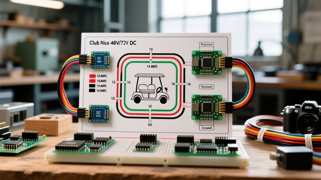
Essential Wire Gauge Specifications by Circuit
A common and dangerous mistake in DIY golf cart repair is using a single wire gauge (often 6 AWG) for the entire cart. A Club Car IQ or Curtis-controlled system features distinct high-amperage traction circuits and low-amperage logic circuits. Sizing wire based on the National Electrical Code (NFPA 70) Article 480 guidelines for storage batteries and DC electronics is critical to preventing voltage drop and thermal runaway.
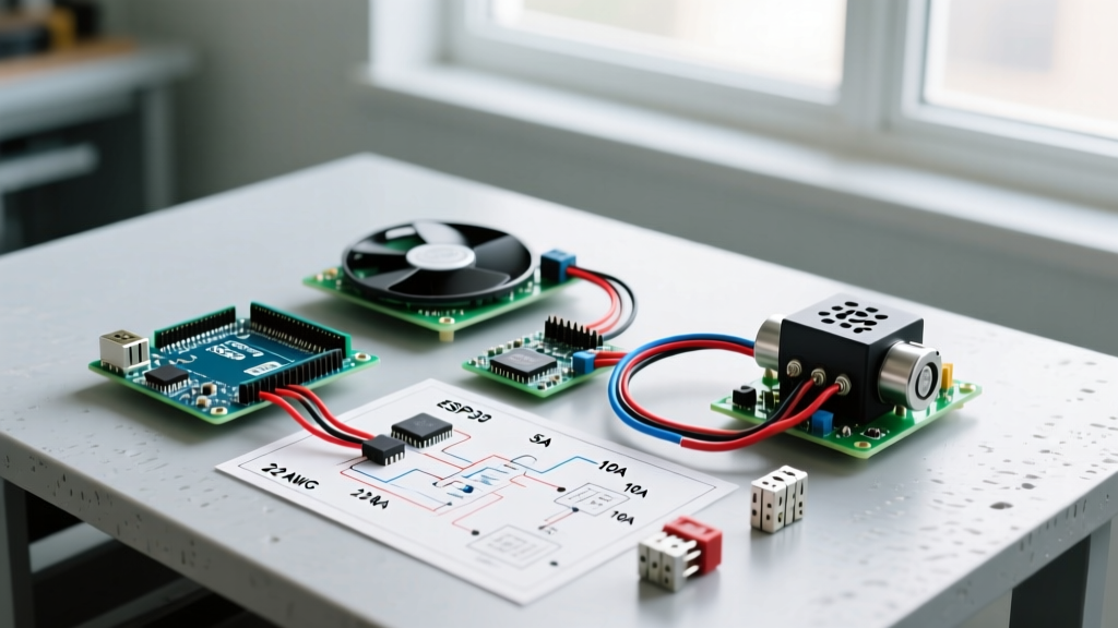
| Circuit Application | Recommended AWG | Peak Amperage | Club Car System Context |
|---|---|---|---|
| Main Battery Bank to Solenoid | 2 AWG (or 1 AWG) | 300A - 450A | Must handle inrush current and sustained hill-climbing loads without exceeding a 3% voltage drop. |
| Solenoid to Controller B+ | 2 AWG | 300A - 450A | Keep this run as short as physically possible to minimize resistance. |
| Controller to Motor Phase Cables | 2 AWG | 300A+ | Carries the raw AC/DC phase current to the drive motor. |
| Main Ground (B- Return) | 2 AWG (or 1 AWG) | 300A - 450A | Often overlooked; a poor ground causes erratic controller behavior and speed sensor faults. |
| Solenoid Activation Coil | 14 AWG | 10A - 15A | Pulls from the key switch/microswitch to close the high-amp solenoid contacts. |
| MCOR / Throttle Pedal Box | 18 AWG | < 1A | Low-voltage logic signals sent to the Curtis or IQ controller. |
| Speed Sensor / Encoder | 18 AWG (Shielded) | < 1A | Shielding is mandatory to prevent EMI from the high-amp phase cables. |
Standard Club Car Color Code Matrix
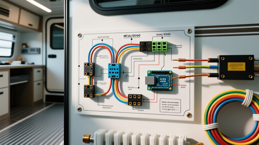
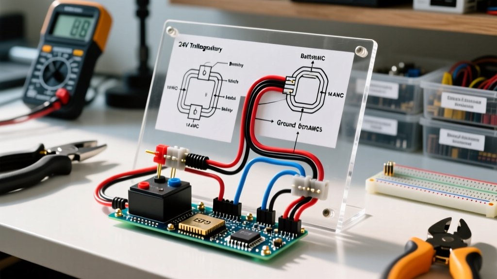
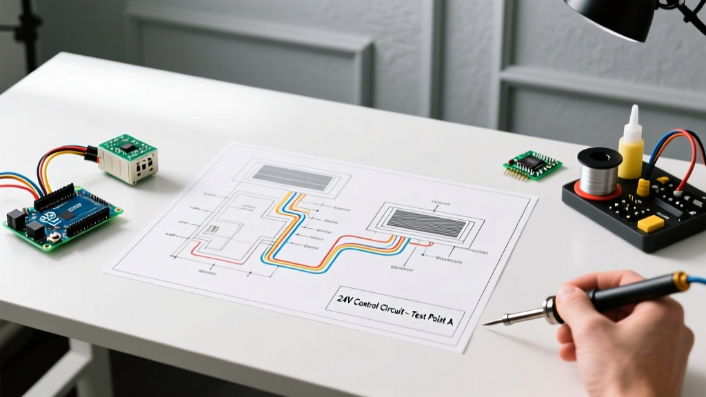
Unlike automotive AC/DC systems that rely on standardized SAE color codes, Club Car utilizes a specific DC logic color palette. While aftermarket harnesses may vary, any OEM electric Club Car wiring diagram from the DS era through the modern Onward lineup will generally adhere to the following matrix:
- Red: Main Battery Positive (B+). Always hot, unfused at the battery pack, fused immediately after the main solenoid or at the controller B+ post.
- Black: Main Battery Negative (B-) / Ground. Routes from the battery pack negative to the controller B- and motor ground.
- Blue: Solenoid Activation. Carries pack voltage from the key switch and microswitches to the solenoid's small activation terminal.
- Yellow: Directional Switch (Forward/Reverse). Routes logic signals from the F/R switch to the controller to dictate motor phase sequencing.
- White: High-Pedal Disable (HPD) / Brake Interlock / Tow-Run Switch. Ensures the cart cannot accelerate if the pedal is already depressed upon key-on.
- Green: Speed Sensor Signal. Carries the pulse-width or frequency signal from the motor encoder back to the controller.
- Orange: 48V/12V Accessory Tap. Often used for the solenoid pre-charge resistor circuit or voltage reducers (DC-DC converters).
Model-Specific Nuances: DS vs. Precedent vs. Onward
The 48V IQ System (Precedent & Late DS)
The IQ system introduced the MCOR (Motor Controller Output Regulator). When wiring the MCOR, the 18 AWG logic wires must be routed away from the 2 AWG motor phase cables. Electromagnetic Interference (EMI) from the phase cables can induce "ghost" voltages in the MCOR signal wire, causing the cart to unexpectedly accelerate or throw an HPD (High Pedal Disable) fault code.
The 72V Lithium Onward & Custom Conversions
As 72V lithium packs (like the 105Ah EVE or Roypow systems) become the standard for 2026 performance builds, the electrical dynamics shift. At 72V, peak amperage can exceed 500A during hard acceleration. Upgrading the main battery cables from 2 AWG to 1/0 AWG is highly recommended to mitigate voltage sag. Furthermore, the Curtis 1268/1238 series controllers commonly used in these builds require precise pre-charge circuits to prevent capacitor inrush from welding the main solenoid contacts.
Critical Failure Modes: When Gauges and Colors Fail
Ignoring the physical realities of DC wiring leads to catastrophic, expensive failures. Here are the most common edge cases we diagnose in the field:
- The Melted Solenoid Post: Caused by using 4 AWG wire on a 300A+ circuit, or failing to torque the solenoid nut to the OEM spec (usually 90-120 in-lbs). The increased resistance generates immense heat, melting the internal coil potting and fusing the contacts permanently ON.
- Controller Low-Voltage Cut-Off (LVC) Under Load: If you use 4 AWG wire for a 10-foot run (20 feet round-trip), the resistance is roughly 0.0049 ohms. At 300A, that creates a 1.47V drop. While that sounds small, in a 48V system sagging under load, it can trick the controller into triggering LVC, abruptly cutting power on steep hills.
- The "Runaway" Cart (Welded Solenoid): Omitting the 470-ohm, 2-watt pre-charge resistor across the large solenoid terminals. When the solenoid closes without a pre-charge, the massive inrush current to the controller's empty capacitors creates an arc that welds the copper contacts together. The cart will continue to drive even when the key is turned off.
Expert Tip: Never use solder on high-amperage DC battery connections. Solder has a lower melting point than copper and can liquefy during a sustained high-amp hill climb, causing the cable to detach and arc. Always use mechanical crimps with a hydraulic crimper.
Step-by-Step High-Amp Termination Best Practices
To ensure your wiring matches the reliability of the schematic, follow this termination protocol for all 2 AWG and larger cables:
- Strip and Clean: Strip the insulation using a precision wire stripper. Do not nick the copper strands. Clean the exposed copper with a brass wire brush to remove oxidation.
- Marine-Grade Terminals: Use only tinned copper, closed-end ring terminals. The tin plating prevents galvanic corrosion, which is rampant in golf carts exposed to moisture and fertilizer.
- Hydraulic Crimping: Use a 6-ton hydraulic crimper with the correct hexagonal die. A hammer-style crimp tool creates voids inside the terminal, leading to internal resistance and heat.
- Adhesive Heat Shrink: Apply 3M or equivalent adhesive-lined (dual-wall) heat shrink over the terminal barrel. When heated, the inner meltable adhesive seals out moisture and battery acid fumes.
- Precision Torque: Use an inch-pound torque wrench. Overtightening a 5/16" solenoid stud can snap the brass stud inside the coil assembly, ruining a $120 component.
Frequently Asked Questions (FAQs)
Can I use automotive primary wire for my Club Car?
No. Automotive wire (GXL/TXL) is designed for 12V/14V systems and high-temperature engine bays, but it lacks the strand count and flexibility required for the tight bending radiuses inside a golf cart battery tray. Use flexible, multi-strand battery cable (often labeled as welding cable or SGX type).
Why does my Club Car wiring diagram show a diode on the solenoid?
Older Club Car DS models with inductive solenoid coils sometimes utilize a flyback diode or a resistor to suppress the voltage spike (back-EMF) generated when the solenoid de-energizes. This protects the delicate microswitches and early-state logic boards from arc damage.
How do I test for voltage drop across my main cables?
Set your multimeter to DC Volts. Place the red probe on the battery post and the black probe on the corresponding controller post. Have an assistant press the throttle (with the rear wheels elevated safely on jack stands). A reading higher than 0.5V indicates excessive resistance, requiring you to check your crimps, cable gauge, and terminal cleanliness.