
The Problem with Direct-to-Battery Wiring
When installing a compact fishfinder, the most common mistake anglers make is bypassing the boat's main DC distribution panel. While the Garmin Striker 4 is a highly efficient unit, clipping its power leads directly to a 12V marine battery with a cheap inline fuse holder violates ABYC E-11 standards and creates a hazardous rat's nest at the battery terminals. As of 2026, with the mass adoption of marine Lithium Iron Phosphate (LiFePO4) batteries and complex BMS (Battery Management Systems), managing DC loads through a centralized breaker panel is no longer optional—it is critical for system safety, clean power delivery, and accurate sonar performance.
Direct-to-battery wiring often leads to ground loops, which introduce alternator whine and fuel pump noise directly into your sonar transducer. Furthermore, inline fuse holders exposed to bilge moisture are a leading cause of marine electrical fires. This guide provides the definitive wiring diagram for Garmin Striker 4 integration into a marine switch panel, ensuring your electronics receive clean, stable, and properly protected DC power.
The Proper Wiring Diagram for Garmin Striker 4 Panel Integration
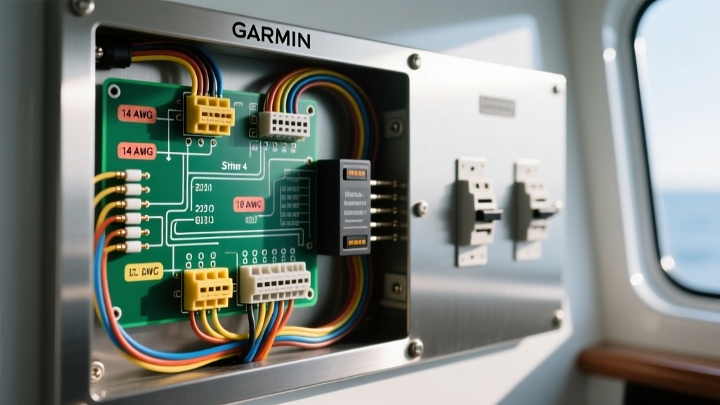
Instead of running a single duplex cable from the battery to the dash, a proper marine electrical system utilizes a centralized DC breaker panel (such as the Blue Sea ST Blade or WeatherDeck series). The panel acts as the distribution hub, housing individual thermal or magnetic breakers for every accessory on the vessel.
Schematic Flow and Logic
- Primary Power Source: Marine deep-cycle battery (12V DC).
- Main Feed: Heavy-gauge cable (typically 4 AWG or 2 AWG) runs from the battery positive terminal to the main positive bus bar on the DC breaker panel, protected by a main Class T fuse within 7 inches of the battery.
- Main Ground: Heavy-gauge cable runs from the battery negative terminal to the panel's negative bus bar.
- Branch Circuit (Striker 4): The Garmin Striker 4 red power wire connects to a dedicated 3A breaker on the panel's positive bus bar.
- Branch Ground (Striker 4): The Garmin Striker 4 black ground wire connects directly to the panel's negative bus bar.
Component Specifications and Sizing Matrix
Sizing your wire and breaker correctly is non-negotiable. The Garmin Striker 4 has a maximum power draw of approximately 0.23 Amps at 12V. While this is a tiny load, wire gauge must be selected based on the total round-trip circuit length to prevent voltage drop, which can cause the fishfinder to reboot at high RPMs when the alternator alters system voltage.
| Component | Specification | Notes & Best Practices |
|---|---|---|
| Wire Gauge | 16 AWG (Minimum 18 AWG) | Use 16 AWG tinned marine wire (e.g., Ancor) for runs up to 20 feet round-trip to eliminate voltage drop. |
| Branch Breaker | 3A Thermal/Magnetic | Garmin recommends a 2A or 3A inline fuse. On a standard panel, a 3A breaker provides exact protection without nuisance tripping. |
| Terminals | #10 Ring, Heat Shrink | Use adhesive-lined heat shrink ring terminals to prevent moisture wicking into the copper strands. |
| Panel Type | Fused Switch Panel | Blue Sea ST Blade (for interior/under-dash) or WeatherDeck (for exposed dash environments). |
Step-by-Step Panel Termination Guide
Executing this wiring diagram requires precision and the right tools. Follow these steps to ensure a factory-grade installation that complies with marine safety standards.
1. Route the Power Cable
Run a high-quality, tinned copper duplex marine wire (red and black jacketed together) from the back of your DC breaker panel to the mounting location of the Garmin Striker 4. Keep this cable routed away from high-current AC wiring, VHF radio coax cables, and the transducer cable to prevent electromagnetic interference (EMI). Secure the wire every 18 inches using UV-resistant cable clamps.
2. Terminate the Panel Side
Strip exactly 1/4 inch of insulation from the red and black wires. Crimp on adhesive-lined #10 ring terminals using a calibrated ratcheting crimper. Apply heat to the terminals until the adhesive sealant oozes out the back, creating a watertight seal. Attach the red wire to the load side of a dedicated 3A breaker, and the black wire to the negative bus bar stud. Torque the bus bar nut to the manufacturer's specification (usually 20-25 in-lbs for #10 studs) to prevent arcing.
3. Terminate the Fishfinder Side
The Garmin Striker 4 power cable comes pre-terminated with bare wires or a specific quick-connect pigtail. If you must splice the cable to reach your panel, use marine-grade heat shrink butt splices. Never use electrical tape or wire nuts in a marine environment, as vibration and moisture will rapidly degrade these connections. For detailed marine electrical standards, refer to the BoatUS marine wiring guidelines, which emphasize the dangers of improper splicing in wet environments.
4. Verify and Test
Before turning on the unit, use a digital multimeter to check the voltage at the panel terminals. You should read between 12.4V and 13.2V depending on your battery state and charging system. Flip the 3A breaker on and power up the Striker 4. Verify that the backlight adjusts and that the sonar returns are clean.
Troubleshooting Sonar Noise and Voltage Drop
Even with a perfect wiring diagram for the Garmin Striker 4, environmental factors on a boat can introduce electrical anomalies. Here is how to diagnose the two most common issues encountered after panel integration.
Eliminating Ground Loop Interference
If you hear a high-pitched whine in your sonar that changes pitch with engine RPM, or if you see horizontal interference lines on the display, you have a ground loop. This occurs when the Striker 4's ground path shares a return wire with a high-draw device like a bilge pump, live well aerator, or stereo amplifier.
Solution: Ensure the black wire from the Striker 4 is terminated on a clean, dedicated stud on the negative bus bar, completely isolated from heavy inductive loads. Never ground the fishfinder to the aluminum dash, the outboard motor casing, or a daisy-chained ground block.
Preventing High-RPM Reboots
If your Striker 4 randomly reboots or shuts off when you accelerate the boat, you are experiencing severe voltage drop. When the engine revs, the alternator engages, and system voltage fluctuates. If your wire gauge is too thin, or if you have a corroded connection at the breaker panel, the voltage reaching the unit drops below its 10V operational threshold.
According to the Blue Sea Systems Circuit Calculator, a 3% voltage drop is the maximum allowable for sensitive marine electronics. For a 15-foot run drawing 0.23A, 18 AWG wire is technically sufficient, but upgrading to 16 AWG provides a vital buffer against connection resistance and aging terminals.
Final Thoughts on Marine Panel Integration
Treating your Garmin Striker 4 as an integrated component of your vessel's DC electrical system rather than an afterthought pays massive dividends in reliability and safety. By utilizing a dedicated 3A breaker on a centralized marine switch panel, you protect your boat from short circuits, eliminate the fire hazard of inline fuse holders in the bilge, and provide your sonar processor with the clean, stable DC voltage it requires to deliver crystal-clear fish arches and bottom contour mapping. Always verify your connections annually, re-torque bus bar terminals as needed, and inspect heat shrink seals for signs of UV degradation or physical abrasion.