
The Critical Role of DPDT Switches in Modern Control Panels
In industrial automation and custom control panel building, the Double Pole, Double Throw (DPDT) switch remains a foundational component for logic control, polarity reversal, and dual-source selection. While programmable logic controllers (PLCs) handle complex sequencing, manual DPDT toggles and rotary cam switches are still heavily specified for fail-safe manual overrides, emergency motor reversing, and localized polarity swapping. Understanding how to properly interpret and execute a wiring diagram for DPDT switch configurations is essential for panel builders, electrical engineers, and maintenance technicians.
As of 2026, the demand for robust, IP67-rated manual overrides in harsh environments (such as wastewater treatment and marine applications) has driven innovation in sealed toggle designs. However, the underlying electrical principles remain unchanged. A miswired DPDT switch in a motor control circuit can result in catastrophic phase-to-phase short circuits, contact welding, or severe arc flash hazards. This guide provides a deep dive into terminal anatomy, specific wiring topologies for DC and AC motors, and critical integration rules governed by the National Electrical Code (NEC).
Terminal Anatomy and Industrial Specifications
A standard DPDT switch features six distinct terminals, typically arranged in two isolated poles. Each pole contains one common input terminal and two output throw terminals. In industrial panel building, you will frequently encounter heavy-duty toggle switches like the Carling Technologies 632152 or rotary cam switches like the Schneider Harmony XB5AD25. As of early 2026, industrial-grade IP65 DPDT components typically range from $22.00 to $65.00 per unit, depending on current rating and bezel material.
Terminal Identification Standards
- Pole 1: Common (C1 or 11), Throw A (NO1 or 12), Throw B (NC1 or 14)
- Pole 2: Common (C2 or 21), Throw A (NO2 or 22), Throw B (NC2 or 24)
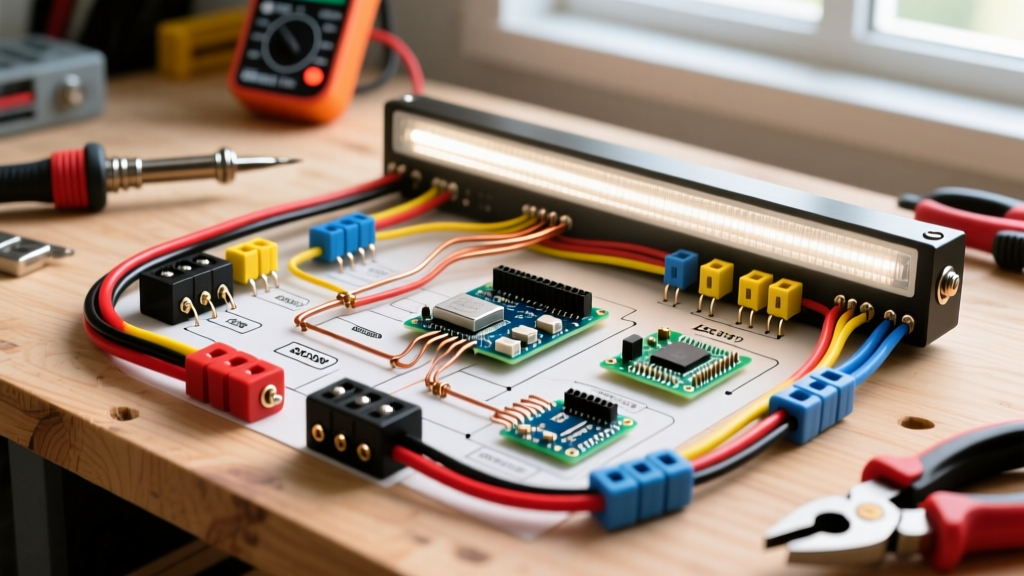
When wiring panel components, always use a calibrated multimeter to verify continuity before energizing. Terminal numbering can vary between IEC (International Electrotechnical Commission) and NEMA (National Electrical Manufacturers Association) standards. Relying solely on printed diagrams without physical verification is a leading cause of panel commissioning failures.
Table 1: Switch Position and Continuity Mapping
| Toggle / Cam Position | Pole 1 Continuity | Pole 2 Continuity | Typical Application State |
|---|---|---|---|
| Position 1 (Up / Left) | C1 to NO1 | C2 to NO2 | Motor Forward / Source A Active |
| Center (Off - if equipped) | Open Circuit | Open Circuit | Safe Isolation / Motor Coast |
| Position 2 (Down / Right) | C1 to NC1 | C2 to NC2 | Motor Reverse / Source B Active |
Step-by-Step Wiring Diagram for DPDT Switch: DC Motor Reversing
Reversing a permanent magnet DC motor requires swapping the polarity of the armature voltage. The DPDT switch is perfectly suited for this, acting as an H-bridge in manual form. This topology is widely used in winch controls, linear actuators, and conveyor overrides.
Wiring Sequence for Polarity Swap
- Power Input: Connect the positive DC supply (+VDC) to the Common terminal of Pole 1 (C1). Connect the negative DC supply (-VDC or Ground) to the Common terminal of Pole 2 (C2).
- Cross-Wiring the Throws: This is the critical step. Wire Throw A of Pole 1 (NO1) to Throw B of Pole 2 (NC2). Then, wire Throw B of Pole 1 (NC1) to Throw A of Pole 2 (NO2). This 'X' crossover is what facilitates the polarity swap.
- Motor Connections: Connect Motor Lead 1 to the junction of NO1 and NC2. Connect Motor Lead 2 to the junction of NC1 and NO2.
- Breaker Integration: Install an appropriately sized DC-rated magnetic circuit breaker (e.g., Eaton FAZ-D10-2) on the main supply lines before the switch to protect against short circuits. DC arcs are notoriously difficult to extinguish; ensure your breaker is specifically rated for DC voltage and polarity.
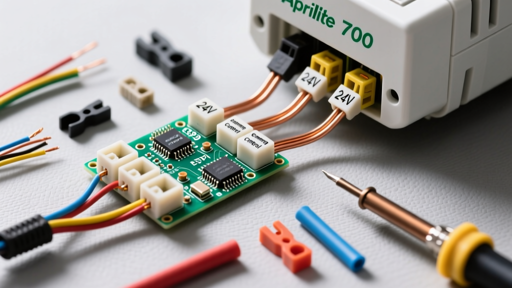
Panel Builder Pro-Tip: When terminating 14 AWG or 12 AWG control wires to a DPDT toggle, always use insulated wire ferrules crimped with a HSC8 6-4A ratcheting tool. Strip the wire to exactly 10mm. Torque the terminal screws to 1.2 Nm (approx. 10.6 in-lbs) using a calibrated torque screwdriver to prevent thermal hotspots and voltage drop under continuous load.
AC Single-Phase Motor Reversing (Start Winding Swap)
Unlike DC motors, you cannot reverse a standard single-phase AC induction motor by simply swapping the main power leads. The direction of rotation is determined by the phase relationship between the main (run) winding and the auxiliary (start) winding. To reverse the motor, you must reverse the polarity of the start winding relative to the run winding.
In a control panel utilizing a DPDT switch for this purpose, the main winding is wired directly across the AC line (L1 and Neutral/L2). The DPDT switch is wired exclusively to the start winding and the series capacitor. The common terminals (C1, C2) receive the AC line and neutral, while the crossed throw terminals connect to the two leads of the start winding. Flipping the switch reverses the current flow through the start winding, shifting the magnetic field phase and reversing the rotor direction. Note: The motor must come to a complete stop before throwing the switch to the reverse position, or the centrifugal switch/internal relay must handle the transition to prevent severe mechanical and electrical stress.
Break-Before-Make vs. Make-Before-Make Contact Timing
When selecting a DPDT switch for a panel wiring diagram, contact timing is a critical, often overlooked specification.
- Break-Before-Make (BBM): The connection to the first throw is physically broken before the connection to the second throw is established. This is mandatory for motor reversing and power source transfer to prevent dead short-circuits across the supply lines.
- Make-Before-Make (MBM): The new connection is made before the old one is broken. This is used in audio signal routing or specific sensor multiplexing where a momentary open circuit would cause a system fault or data loss. Never use an MBM switch for power polarity reversal.
Panel Breaker Integration and NEC Article 430 Compliance
Integrating a manual DPDT switch into a motor control panel requires strict adherence to the NFPA 70 National Electrical Code (NEC), specifically Article 430, which governs motors and motor controllers.
Inverse-Time Breaker Sizing for Motor Branch Circuits
The DPDT switch itself is a controller, not an overcurrent protection device. The branch circuit short-circuit and ground-fault protection must be handled by a circuit breaker or fuses upstream. According to NEC Article 430.52, the maximum rating for an inverse-time circuit breaker protecting a single motor is generally 250% of the motor's Full Load Amps (FLA).
Example Calculation: If you are wiring a 1/2 HP, 120V single-phase motor with an FLA of 9.8A, the maximum standard inverse-time breaker size is 9.8A x 2.50 = 24.5A. You would select the next standard breaker size down, which is a 20A breaker, or up to a 25A breaker if the 20A trips during startup. The DPDT switch must have a continuous current rating (e.g., 20A or 30A) that exceeds the motor FLA and is rated for horsepower (HP) duty, not just resistive amperage.
For comprehensive safety standards regarding panel enclosures and general wiring methods, panel builders must also comply with OSHA 1910.303 General Electrical Requirements, which mandate that all internal panel wiring be neatly routed through wire ducts, properly supported, and protected from sharp metal edges.
Real-World Failure Modes and Edge Cases
Even with a perfect wiring diagram for DPDT switch layouts, physical and environmental factors can cause system failures. Below is a troubleshooting matrix for common field issues.
Table 2: DPDT Panel Troubleshooting Matrix
| Symptom | Probable Root Cause | Corrective Action |
|---|---|---|
| Breaker trips instantly upon switching to Reverse. | Make-before-make contact timing used, or cross-wiring shorted. | Verify BBM switch type. Check for crossed wires at the throw terminals. |
| Switch operates hot / melting terminal block. | Loose terminal torque or using a resistive-rated switch on an inductive motor load. | Retorque to 1.2 Nm. Replace with an HP-rated switch (e.g., Eaton E22D). |
| Motor hums but does not start in Reverse. | Start winding connection lost; centrifugal switch failure in AC motor. | Test continuity of start winding circuit. Inspect motor internal capacitor. |
| Arc flash / pitting on switch contacts. | Switching high inductive loads without arc suppression or snubber circuits. | Install RC snubber networks across the motor terminals to suppress inductive kickback. |
Summary and Best Practices
Designing and executing a reliable wiring diagram for DPDT switch applications requires more than just connecting wires to terminals. It demands a thorough understanding of contact timing (BBM vs. MBM), proper NEC breaker sizing for inductive loads, and meticulous physical termination practices like ferrule crimping and torque verification. By selecting the correct industrial-rated components and adhering to NFPA and OSHA standards, panel builders can ensure safe, long-lasting motor control and power transfer systems that withstand the rigors of modern industrial environments.