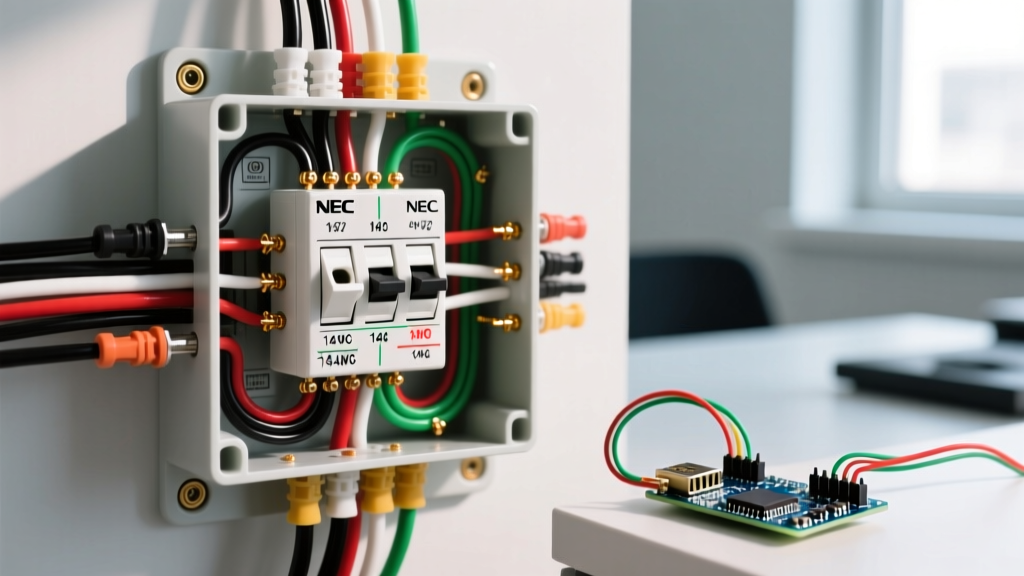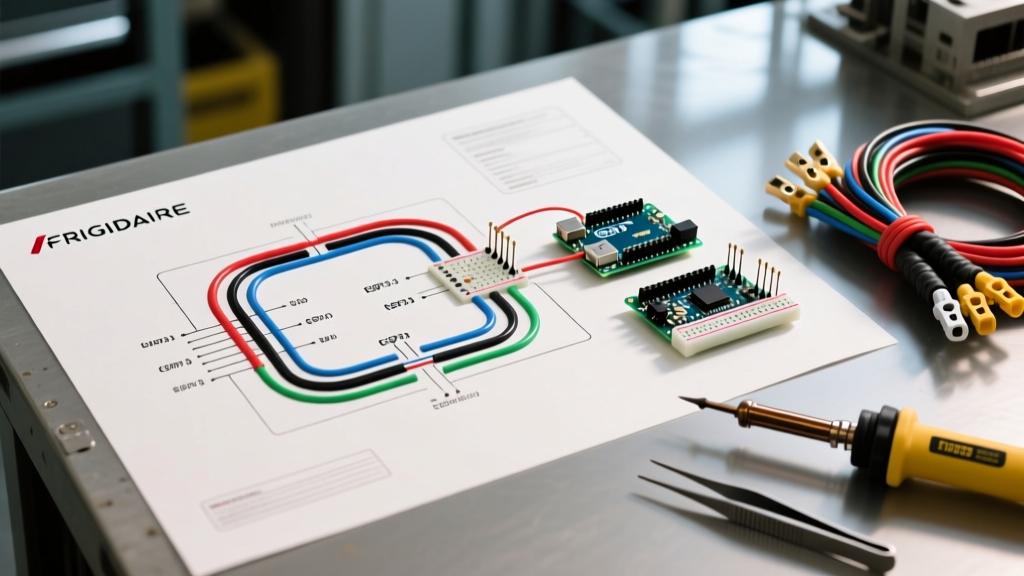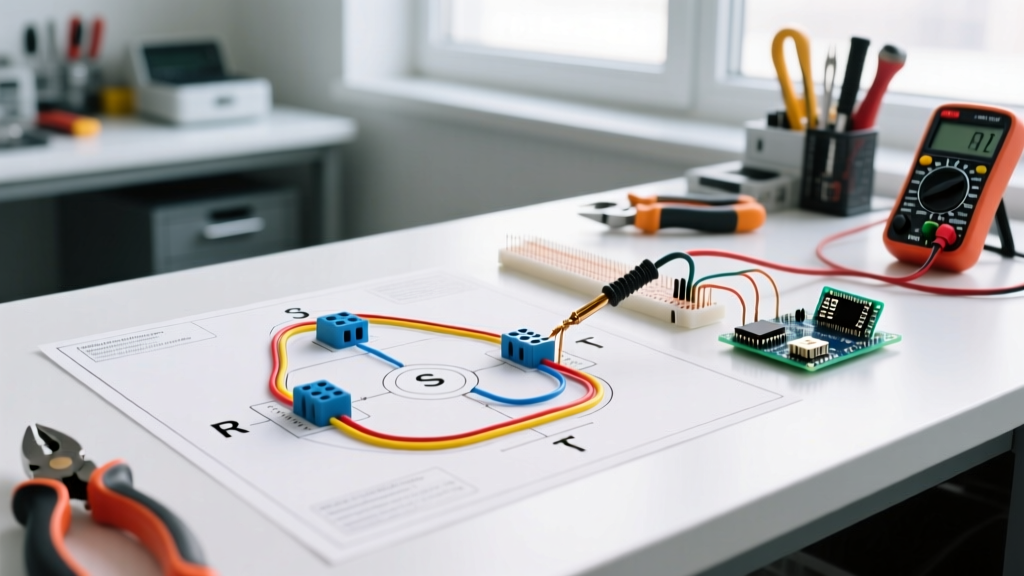

Why Choose a Delta Configuration for 3-Phase Motors?
In industrial and commercial applications, the 3-phase delta wiring diagram for a motor is the standard for high-torque, continuous-duty operations. Unlike the Wye (star) configuration, which reduces starting voltage and current, a delta connection applies full line voltage across each motor winding. This results in higher starting torque and greater power output, making it ideal for heavy machinery, conveyor systems, and industrial compressors. As of 2026, with the widespread adoption of IE4 and IE5 premium efficiency motors (such as the WEG W22 and Baldor-Reliance Ultra-E series), proper delta wiring is critical to ensuring these high-efficiency units operate within their designed thermal limits.
This comprehensive walkthrough will guide you through the exact steps to wire a 3-phase motor in a delta configuration, covering terminal mapping, conductor sizing, and critical torque specifications to prevent catastrophic failure modes.
Pre-Wiring Safety and Tool Requirements
Before opening any terminal box, strict adherence to NFPA 70E electrical safety standards is mandatory. Working on 3-phase systems (typically 230V, 460V, or 575V) presents severe arc flash and shock hazards.
Required Tools and PPE
- Multimeter: A True-RMS CAT III or CAT IV multimeter (e.g., Fluke 87V) for verifying zero energy state.
- Insulation Tester: A megohmmeter (e.g., Fluke 1587) to test winding insulation prior to energizing.
- Torque Screwdriver: Calibrated to measure between 1.0 Nm and 6.0 Nm for terminal lug tightening.
- Wire Strippers and Ferrule Crimper: For preparing stranded conductors with DIN 46228 pin ferrules.
- PPE: Arc-rated clothing and voltage-rated gloves appropriate for the specific incident energy level of your panel.
Pro-Tip: Never rely solely on a motor starter's 'OFF' indicator. Always perform a live-dead-live test with your multimeter at the motor's terminal block to verify the Lockout/Tagout (LOTO) procedure was executed correctly.
Decoding the Terminal Box: IEC vs. NEMA Standards
The physical wiring of a delta connection depends heavily on whether your motor follows IEC (International Electrotechnical Commission) or NEMA (National Electrical Manufacturers Association) naming conventions. Understanding the NEMA MG-1 Standard and IEC 60034 is crucial for interpreting the delta wiring diagram for a motor correctly.
IEC 6-Lead Terminal Layout
Most modern global motors use a 6-lead IEC terminal block. The windings are labeled as follows:
- U1, V1, W1: The start of windings 1, 2, and 3.
- U2, V2, W2: The finish of windings 1, 2, and 3.
NEMA 3-Lead vs. 9-Lead Layout
Single-voltage NEMA motors typically have 3 leads (T1, T2, T3), which are internally connected in either delta or wye at the factory. If you are wiring a 9-lead dual-voltage NEMA motor for low-voltage delta operation, you must use a specific parallel-delta jumper configuration (connecting T1-T6-T7, T2-T4-T8, and T3-T5-T9). For this guide, we will focus on the standard 6-lead IEC layout, which is the most common scenario requiring manual delta jumpers in the field.
Step-by-Step Delta Wiring Walkthrough
Follow these precise steps to configure a standard 6-lead IEC motor into a delta connection.
Step 1: Prepare the Conductors and Ferrules
Strip the incoming 3-phase power cables to the exact length required by the terminal block depth (usually 12mm to 15mm). Crimp insulated pin ferrules onto the stranded wire ends. This prevents strand fraying, ensures uniform contact pressure, and mitigates the risk of a loose strand causing a phase-to-phase short inside the terminal box.
Step 2: Install the Delta Jumpers (Links)
The core of the delta wiring diagram for a motor is the creation of three closed loops using copper jumper links. You must connect the start of one winding to the finish of the adjacent winding:
- Connect U1 to W2.
- Connect V1 to U2.
- Connect W1 to V2.
Ensure the jumper links are seated flat against the terminal studs. If your motor did not come with factory copper links, use copper busbar strips or appropriately rated (600V) insulated jumper wires of the same gauge as your supply conductors.
Step 3: Connect the Line Voltage
With the delta loop established, apply the 3-phase line voltage to the remaining open terminals. While phase sequence (L1, L2, L3 to U1, V1, W1) does not affect the delta connection's electrical validity, it does dictate the motor's direction of rotation.
- Connect Phase L1 to terminal U1 (which is now jumpered to W2).
- Connect Phase L2 to terminal V1 (which is now jumpered to U2).
- Connect Phase L3 to terminal W1 (which is now jumpered to V2).
Step 4: Torque and Verify
This is where most field failures occur. According to NFPA 70 (NEC) guidelines and general mechanical best practices, all electrical connections must be torqued to the manufacturer's specifications. For standard M5 terminal studs, apply 2.5 Nm to 3.0 Nm of torque. For M6 studs, apply 4.0 Nm to 5.0 Nm. Under-torquing leads to micro-arcing and thermal runaway; over-torquing strips the brass threads or shears the stud.
Conductor Sizing and Overcurrent Protection Matrix
Selecting the correct wire gauge and breaker size is critical. The table below provides baseline sizing for 460V, 3-phase delta motors based on NEC Table 430.250 and standard 75°C copper conductor ampacity. Always verify against the specific motor nameplate Full Load Amps (FLA).
| Motor HP | Approx. FLA (460V) | Min. Copper Wire (AWG) | Max Breaker Size (Inverse Time) |
|---|---|---|---|
| 5 HP | 7.6 A | 14 AWG | 20 A |
| 10 HP | 14 A | 12 AWG | 35 A |
| 15 HP | 21 A | 10 AWG | 50 A |
| 25 HP | 34 A | 8 AWG | 80 A |
| 50 HP | 65 A | 4 AWG | 150 A |
Note: If the motor is located more than 100 feet from the panel, you must calculate voltage drop and potentially upsize the conductors by one or two AWG sizes to maintain a drop below 3%.
Real-World Failure Modes and Diagnostics
Even with a perfect delta wiring diagram for a motor, environmental and mechanical factors can cause failures. Here is how to diagnose the most common edge cases.
1. Single-Phasing
If one phase of the supply is lost (due to a blown fuse or failed contactor pole), a delta-connected motor will continue to run but will draw excessive current in the remaining two phases, quickly burning out the windings. Diagnostic: Use a clamp meter to measure current on all three lines while the motor is under load. If one reads 0A and the others read 1.5x to 2.0x FLA, you have single-phasing. Install a solid-state phase monitor relay to prevent this.
2. Insulation Breakdown from VFD Reflections
If your delta-wired motor is fed by a Variable Frequency Drive (VFD), the high-frequency PWM pulses can cause voltage reflection, leading to corona discharge and winding insulation failure. Diagnostic: Use a megohmmeter (set to 500V DC for motors under 600V) to test phase-to-ground insulation. As highlighted in the Fluke Motor Troubleshooting Guide, healthy windings should read greater than 100 Megohms. If the reading is below 2 Megohms, the winding insulation is compromised and the motor must be rewound or replaced. For VFD applications, always use inverter-duty motors with enhanced dielectric insulation.
3. Thermal Overload Tripping
If the motor's external overload relay trips repeatedly, do not simply increase the trip setting. Check for mechanical binding in the driven load, verify the ambient temperature does not exceed the motor's design (typically 40°C), and ensure the cooling fan is intact. In a delta configuration, the phase current inside the windings is 58% (1/√3) of the line current; ensure your overload relay is placed in the line side and dialed precisely to the nameplate FLA, not the service factor maximum.
Final Verification Checklist
Before removing LOTO and energizing the system, run through this final checklist:
- All three delta jumpers are securely in place (U1-W2, V1-U2, W1-V2).
- Line phases L1, L2, L3 are connected to U1, V1, W1.
- All terminal nuts are torqued to spec (e.g., 3.0 Nm for M5).
- No stray wire strands are bridging terminals.
- Insulation resistance test (Megger) passed (>100 MΩ).
- Motor overload relay is set exactly to the nameplate FLA.
By following this rigorous step-by-step walkthrough, you ensure your 3-phase delta motor wiring is safe, compliant with current electrical codes, and optimized for long-term industrial reliability.