
Mastering the K6 Architecture: A Diagnostic Approach
The 2006 Suzuki GSX-R600 (chassis code K6) marked a significant generational shift, introducing a lighter twin-spar aluminum frame, an underseat exhaust, and a completely revised engine management system. However, the core electrical architecture retained Suzuki’s proven, albeit complex, routing logic. When diagnosing parasitic draws, charging system failures, or starter interlock faults, generic advice is useless. You need the electrical 2006 GSXR 600 wiring diagram to trace specific pinouts, verify wire gauge integrity, and isolate component-level failures.
In 2026, the K6 is considered a legacy sportbike. Wiring harnesses are now approaching two decades of heat cycling, vibration, and exposure to the elements. Dielectric grease dries out, connector pins corrode, and aftermarket modifications introduce hidden shorts. This guide bypasses basic forum guesswork and provides a structured, diagram-driven troubleshooting methodology using precise multimeter data and OEM specifications.
Safety & Multimeter Calibration Protocol
Before probing the K6 harness, ensure your digital multimeter (DMM) is calibrated. Use a CAT III rated meter (like the Fluke 117) for automotive/motorcycle applications. Always disconnect the negative battery terminal before performing continuity or resistance tests to prevent blowing the DMM’s internal fuse or damaging the K6’s sensitive Engine Control Module (ECM).
Decoding the Diagram: Suzuki Wire Color Standards
The factory service manual and the electrical 2006 GSXR 600 wiring diagram rely on a strict color-coding matrix. Unlike some European manufacturers that use complex tracer patterns, Suzuki primarily uses solid colors or a base color with a single tracer stripe. Misidentifying a Black/White (Ground) as a solid Black (often switched power in other applications) will result in immediate short circuits.
| Wire Color | Function / Circuit | Diagnostic Notes |
|---|---|---|
| Red | Unswitched Battery Positive | Constant 12V. Routes directly from battery to main fuse and starter relay. |
| Black/White | Chassis Ground | Must show < 0.5Ω to battery negative. High resistance here causes ECM resets. |
| Orange/White | Switched Ignition Power | 12V only when key is ON. Powers fuel pump relay, ECM, and dash. |
| Yellow (x3) | Stator AC Output (3-Phase) | Routes from alternator to Rectifier/Regulator. Never test with engine running on Ohms setting. |
| White/Black | Starter Signal / Interlock | Carries 12V from starter button through clutch switch to starter relay coil. |
| Pink | Diagnostic / SDS Output | Connects to Suzuki Diagnostic System (SDS) tool or manual blink-code jumper. |
Step-by-Step Troubleshooting: Common K6 Failure Modes
Using the wiring diagram as your map, we can systematically isolate the three most prevalent electrical failures on the 2006 GSX-R600.
1. The 5-Pin Rectifier Connector Melt & Stator Burnout
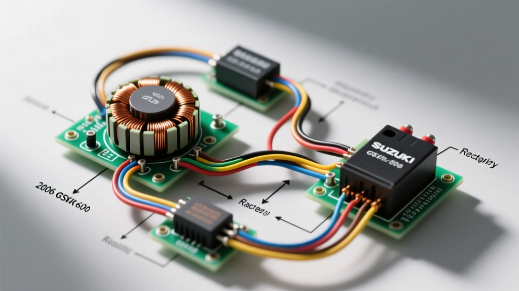
The K6 uses a 3-phase permanent magnet alternator. The stator outputs raw AC voltage, which the Rectifier/Regulator (R/R) converts to DC and clamps at ~14.4V. The notorious failure point on the 2006-2007 models is the 5-pin harness connector leading to the R/R. Due to its proximity to the underseat exhaust and high current flow (often exceeding 30 Amps), the standard Suzuki terminals overheat, increasing resistance and eventually melting the plastic housing.
Diagnostic Sequence:
- Visual Inspection: Disconnect the 5-pin R/R connector. Look for brown/black scorch marks on the three Yellow wire terminals. If melted, the harness pigtail and R/R must be replaced (OEM R/R part #32800-47H00 typically costs $180-$220 in 2026).
- Stator Resistance Test (Engine OFF): Set DMM to 200Ω. Probe Yellow-to-Yellow wires at the stator side of the connector. You should read between 0.2Ω and 1.0Ω across all three combinations (Y1-Y2, Y2-Y3, Y1-Y3).
- Stator Ground Test: Set DMM to 20MΩ. Probe each Yellow wire to the engine case. The reading must be OL (Over Limit / Infinite). Any continuity indicates a burnt stator winding shorted to the stator core.
- AC Output Test (Engine ON): Set DMM to VAC. Reconnect stator, back-probe the Yellow wires at the R/R connector. Rev to 5,000 RPM. You should see 50V to 70V AC between phases. If voltage drops significantly under load, the stator magnets have demagnetized or the windings are failing.
Expert Insight: According to technical bulletins from Electrosport Industries, upgrading to a MOSFET-style regulator (like the SH775) drastically reduces heat output compared to the stock K6 shunt-style regulator, extending the life of the 5-pin connector and stator.
2. Starter Relay and the Clutch/Sidestand Interlock Logic
The K6 will not crank if the sidestand is down (unless in neutral), and it requires the clutch to be pulled in if in gear. This logic is hardwired through a series of switches before reaching the starter relay coil. When the starter button is pressed and nothing happens, amateurs replace the starter motor. Professionals use the electrical 2006 GSXR 600 wiring diagram to trace the interlock circuit.
Tracing the Interlock Path:
- Power Source: 12V leaves the ignition switch on the Orange/White wire.
- Engine Stop Switch: Routes through the right handlebar kill switch (must be in 'Run').
- Starter Button: Exits the left switchgear on a Black/Red wire when pressed.
- Clutch Switch: The Black/Red wire enters the clutch lever microswitch. If the lever is pulled, it exits on a White/Black wire.
- Sidestand/Neutral Logic: The White/Black wire splits. It can bypass the sidestand relay ONLY if the neutral switch (Green/Black wire at the transmission case) provides a ground path, completing the circuit to the starter relay's negative coil terminal.
The Fix: If the dash shows 'N' (Neutral) but the bike won't crank without pulling the clutch, the neutral switch on the engine case is fouled with oil sludge, or the sidestand relay under the seat has corroded internal contacts. Bypass the sidestand relay temporarily with a jumper wire to confirm, then replace the relay.
3. Tip-Over Sensor (TOS) and Fuel Pump Prime Failure
When you turn the K6 ignition to 'ON', you should hear the fuel pump prime for exactly 3.0 seconds. If it doesn't, and the dash is lit, the ECM may be inhibiting the fuel pump relay due to a faulty Tip-Over Sensor. The TOS is a mercury-free roller switch located under the tank.
The TOS has three wires: Black/White (Ground), Orange/White (12V Input), and White/Black (Signal to ECM). If the sensor is stuck in the 'tipped' position, it sends a 0V signal to the ECM instead of the expected 12V, prompting the ECM to immediately kill the fuel pump relay and ignition coils. Use the wiring diagram to locate the ECM connector (Pin 12 for the TOS signal on the K6 harness). Back-probe Pin 12 with the key ON; if it reads 0V while the bike is upright, replace the TOS unit.
Edge Cases: Aftermarket Harness Degradation
Many 2006 GSX-R600s on the road in 2026 have undergone tail-tidy conversions, aftermarket LED indicator swaps, or alarm system installations. These modifications frequently involve cutting into the main harness near the rear subframe. When using the wiring diagram to troubleshoot a parasitic battery drain, pay special attention to the rear lighting connector. Scotch-locks and electrical tape degrade rapidly under a sportbike seat, allowing moisture ingress that creates high-resistance parallel paths to ground. Always solder and use adhesive-lined heat shrink (minimum 3:1 shrink ratio) when repairing K6 harness cuts.
Authoritative References & OEM Data
For exact pinout matrices, torque specifications for grounding bolts, and visual routing schematics, always cross-reference your physical multimeter readings with verified OEM documentation. You can view the factory harness routing and component breakdown via the Partzilla 2006 GSX-R600 Wiring Harness Catalog. Additionally, maintaining the YT12A-BS battery with a smart maintainer is critical for K6 ECM health; refer to the Battery Tender Technical Information database for proper desulfation and charging protocols for AGM motorcycle cells.
By treating the electrical 2006 GSXR 600 wiring diagram not just as a picture, but as a logical flowchart of voltage and resistance, you can diagnose and repair the K6’s electrical system with factory-level precision.