
Decoding the 2015-2020 Ford F-150 SYNC 3 Stereo Architecture
Upgrading the head unit in a 13th-generation Ford F-150 (2015–2020) equipped with the factory 8-inch SYNC 3 infotainment system is far from a simple plug-and-play endeavor. Unlike older vehicles where a basic 12V power, ground, and speaker wire harness sufficed, the modern F-150 integrates the Audio Control Module (ACM) deeply into the vehicle's MS-CAN and HS-CAN data networks. To retain critical factory features—such as steering wheel controls (SWC), the backup camera, climate control pop-ups, and door chimes—you need a highly specific wiring diagram for stereo integration that accounts for data bus translation.
In this comprehensive vehicle-specific guide, we break down the exact pinouts, required CAN-bus adapters, and advanced troubleshooting steps to ensure your aftermarket stereo upgrade (whether you are installing a Pioneer DMH-WT8600NEX, Alpine iLX-W650, or Kenwood eXcelon) functions flawlessly without triggering dashboard fault codes.
⚠️ CRITICAL WARNING: Do Not Cut the Factory HarnessThe F-150's ACM is tied to the Passive Anti-Theft System (PATS) and the Instrument Panel Cluster (IPC). Splicing directly into the factory 54-pin Quadlock connector without a data-retention module will result in a U0155 Diagnostic Trouble Code (Lost Communication With Instrument Panel Cluster), loss of door-ajar chimes, and a parasitic battery drain that will kill your truck's battery overnight.
Choosing the Right Data Retention Adapter
Before consulting the physical wiring diagram, you must select the correct interface module. The adapter acts as the translator between the Ford CAN-bus and the aftermarket head unit's data port. Below is a comparison of the top-tier adapters available for the SYNC 3 platform in 2026.
| Adapter Model | Avg. Price (2026) | SYNC 3 Vehicle Settings | Backup Camera & USB |
|---|---|---|---|
| iDatalink Maestro RR2 | $159.99 | Full Retention (via HU screen) | Requires ACC-CAM-FD & ACC-USB-FD2 |
| Axxess AXTO-FD01 | $69.99 | Basic Chime Retention Only | Standard CVBS Video Trigger |
| Metra 40-FD11 | $49.99 | Not Supported | Antenna & Basic Data Only |
Expert Recommendation: For a seamless 2026 installation, the iDatalink Maestro RR2 is the undisputed standard. It flashes custom firmware to your specific head unit model, allowing you to change factory vehicle settings (like door lock logic and lighting delays) directly from your new aftermarket touchscreen.
The 54-Pin Quadlock Wiring Diagram for Stereo Integration
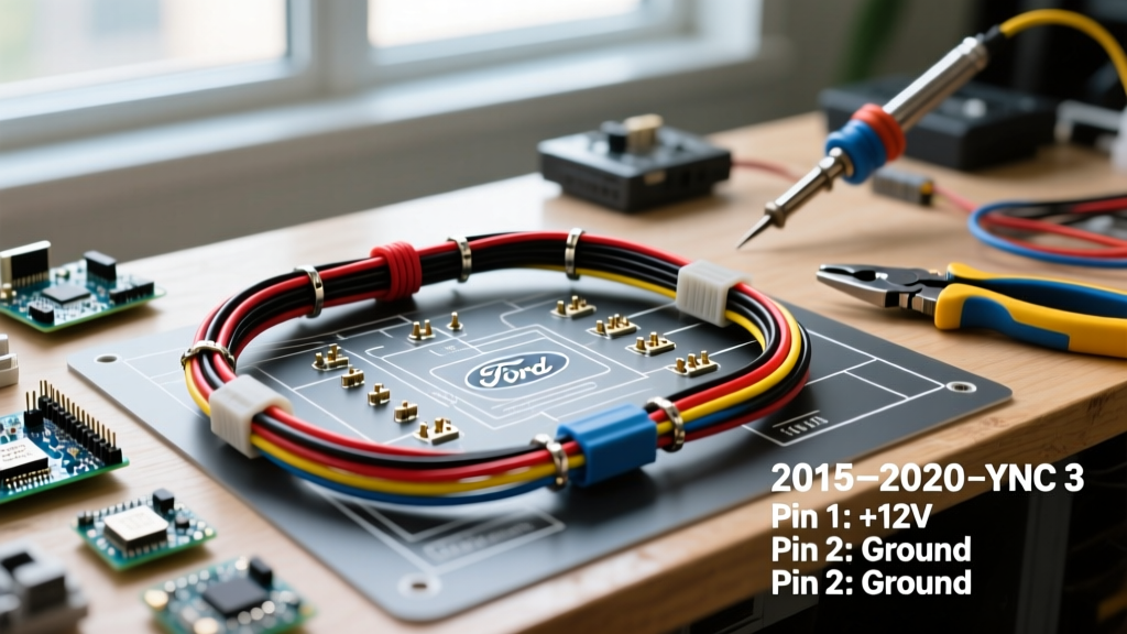
The factory SYNC 3 radio connects to the vehicle via a 54-pin Quadlock connector. When using a Maestro RR2 or Axxess harness, the adapter plugs inline between the factory plug and the ACM. Below are the critical vehicle-side pinouts that the adapter intercepts to translate data and power.
Power, Ground, and CAN-Bus Pinout
| Quadlock Pin | Wire Color | Function / Signal | Multimeter Expected Value |
|---|---|---|---|
| Pin 1 | Gray/Orange | MS-CAN High (+) | 2.5V - 3.5V (Active) |
| Pin 2 | Gray/Brown | MS-CAN Low (-) | 1.5V - 2.5V (Active) |
| Pin 14 | Yellow/Green | 12V Constant Battery (B+) | ~12.6V (Engine Off) |
| Pin 15 | Black/Green | Chassis Ground | < 0.1 Ohms to Chassis |
| Pin 25 | Orange/Black | Illumination / Dimmer | 0V - 12V (PWM Signal) |
Speaker Wire Mapping (Non-Amplified SYNC 3)
If your F-150 does not have the factory Sony 390W amplified system, the speaker outputs are low-level (pre-amp) or standard high-level directly from the ACM. The adapter harness will map to the standard EIA/CEA-760 aftermarket color code:
- Front Left: White (+) / White with Black Stripe (-)
- Front Right: Gray (+) / Gray with Black Stripe (-)
- Rear Left: Green (+) / Green with Black Stripe (-)
- Rear Right: Purple (+) / Purple with Black Stripe (-)
Note: If your truck has the Sony Amplified system, the factory ACM outputs low-level balanced differential signals. You must use an adapter specifically wired for amplified systems (like the Maestro HR or Axxess AXTO-FD02) to convert these to standard RCA pre-outs, otherwise, your audio will suffer from severe alternator whine and clipping.
Retaining Factory USB Ports and the Backup Camera
One of the most overlooked aspects of the F-150 stereo wiring diagram is the retention of the center console USB hubs and the tailgate backup camera.
The USB Passthrough Solution
The factory SYNC 3 system uses a proprietary USB-A hub located in the center console and media bin. Standard aftermarket stereos come with a short USB pigtail that hangs out of the dash. To retain the factory USB ports for Apple CarPlay and Android Auto, you must integrate the iDatalink ACC-USB-FD2 cable (~$39.99). This cable intercepts the factory USB data lines from the 54-pin connector and routes them cleanly to the back of your Pioneer or Alpine head unit.
Backup Camera Triggering
The 2015-2020 F-150 backup camera is powered by the Body Control Module (BCM) when the vehicle is shifted into reverse. The CAN-bus adapter reads this data packet and outputs a standard 12V reverse trigger wire (usually Violet/White on the Maestro harness) to the aftermarket head unit's "Reverse In" wire. Ensure you connect this to the head unit's reverse trigger, not directly to the tail light circuit, as the F-150 uses PWM (Pulse Width Modulation) for the tail lights, which will cause the camera feed to flicker or fail entirely.
Troubleshooting Common Failure Modes & Edge Cases
Even with the correct wiring diagram for stereo installation, edge cases occur. Here is how to diagnose the most common issues reported by professionals and the F-150Forum audio community.
1. Parasitic Battery Drain (CAN-Bus Sleep Failure)
Symptom: The truck battery dies after sitting for 24-48 hours.
Cause: The aftermarket head unit or the Maestro module is failing to detect the CAN-bus "sleep" command, keeping the data network awake.
Fix: Connect a digital multimeter in series with the negative battery terminal (set to 10A). Close all doors, lock the truck with the key fob, and wait 20 minutes. The draw should drop below 35mA. If it remains above 150mA, verify that the Maestro firmware was flashed for your exact head unit model and that the 3.5mm data cable is securely seated.
2. U0155 Code & Missing Door Chimes
Symptom: The instrument cluster displays a warning, and opening the door with the keys in the ignition produces no chime.
Cause: The MS-CAN network is interrupted, or the ACM is not responding to the IPC's polling requests.
Fix: Check Pins 1 and 2 on the Quadlock connector. Ensure the adapter's T-harness pins are fully depressed and locked. A loose Gray/Orange MS-CAN High wire will immediately drop the ACM off the network.
3. Steering Wheel Controls (SWC) Not Responding
Symptom: Volume and track buttons on the steering wheel do nothing.
Cause: Incorrect firmware flash or using the 3.5mm SWC jack instead of the data cable.
Fix: When using the Maestro RR2 with a compatible head unit (e.g., Kenwood eXcelon series), SWC signals are transmitted digitally via the Maestro data port. You must leave the 3.5mm SWC jack unplugged and disabled in the head unit's settings menu to prevent signal conflicts.
Expert Wiring Practices for a Factory-Like Finish
To ensure long-term reliability and prevent dash rattles, adhere to these professional installation standards:
- Abandon T-Taps: Never use scotch locks or T-taps on the F-150's CAN-bus wires. The MS-CAN network is highly sensitive to voltage drops and impedance changes. Always use the provided T-harnesses. If a wire must be extended, solder the connection and seal it with 3M FP-301 adhesive-lined heat shrink.
- Fleece Tape Wrapping: The factory Ford harnesses are wrapped in corrugated loom and fleece tape to prevent buzzing against the metal dash frame. Wrap your newly created adapter harness in Tesa 51036 PET fleece tape before zip-tying it behind the climate controls.
- Antenna Adaptation: The F-150 uses a proprietary Motorola antenna connector. You will need a Metra 40-FD11 or equivalent antenna adapter. Furthermore, because the factory antenna amplifier requires 12V phantom power, ensure your adapter's blue "Antenna Trigger" wire is connected to the head unit's blue/white "System Remote Control" wire, not the standard power antenna wire.
"The difference between a frustrating install and a flawless upgrade in the 13th-Gen F-150 comes down to respecting the data bus. Treat the CAN-bus wires with the same care you would treat a fiber optic line, and always verify your adapter's firmware matches the head unit's exact SKU before dismantling the dash."
— Senior Automotive Electronics Technician, Crutchfield Vehicle Fit Database
Final Thoughts on the F-150 Stereo Upgrade
Navigating the wiring diagram for stereo replacement in a SYNC 3-equipped Ford F-150 requires patience, the right data-retention hardware, and a respect for the vehicle's multiplexed networks. By utilizing the Maestro RR2, verifying your Quadlock pinouts, and properly retaining your USB and camera feeds, you can bring modern wireless CarPlay and Android Auto to your truck while maintaining 100% of the factory vehicle diagnostics and safety chimes. Always disconnect the negative battery terminal before beginning work, and keep a digital copy of your adapter's firmware flash on your phone for future reference.