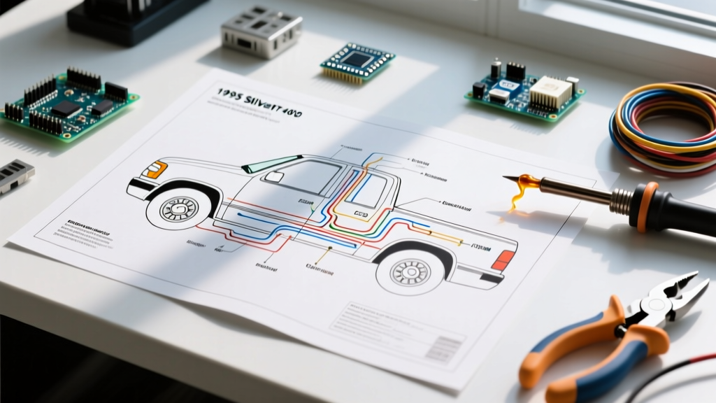

Decoding the 1995 Chevy Silverado (GMT400) Electrical Architecture
The 1995 model year represents a unique transitional period for General Motors' legendary GMT400 platform. When interpreting a wiring diagram for 1995 Chevy Silverado trucks, technicians must account for the split between legacy and modernized systems. While the exterior lighting and chassis grounds remain largely unchanged from the late 1980s, the powertrain control modules (PCM/ECM) and interior dash layouts saw significant revisions. As of 2026, restoring or troubleshooting these 30-year-old harnesses requires an understanding of GM's specific color-coding logic and the physical degradation points inherent to this generation.
TBI vs. CPI Engine Management Wiring
Before tracing any circuit, identify your engine's fuel delivery system, as the wiring harnesses differ drastically:
- 5.0L (305) and 5.7L (350) V8s: These utilize Throttle Body Injection (TBI). The ECM (typically housed under the glovebox) relies on a simpler, lower-pin-count connector with heavy-gauge injector driver wires.
- 4.3L V6: This engine uses Central Port Injection (CPI). The harness features a dedicated fuel pump relay circuit with an oil pressure sender bypass, and a bulkier ECM harness routing to the 'Poppy' valve solenoid under the intake plenum.
Essential Diagnostic Tools for 2026 Restorations
Working on brittle, three-decade-old GM insulation requires precision. Guessing with a test light can fry a replacement ECM. Equip your bench with the following:
- Fluke 87V Industrial Multimeter ($320 - $350): Essential for measuring voltage drop across aging bulkhead connectors. Its high-impedance inputs prevent false ghost-voltage readings on multiplexed GM circuits.
- Power Probe IV ($250 - $280): Ideal for injecting power into the GMT400's blower motor or cooling fan relays without back-probing and damaging weather-pack terminals.
- Permatex 22058 Dielectric Tune-Up Grease ($8): Mandatory for every weather-pack connection you disconnect to prevent future galvanic corrosion.
Step-by-Step Walkthrough: Tracing the Headlight & Multifunction Switch Circuit
The most notorious electrical flaw in the 1995 Silverado is the headlight circuit routing. Unlike modern vehicles that use relays for high-current lighting, the GMT400 routes full headlight amperage directly through the dash switch, up the steering column, and into the multifunction (turn signal) switch. This causes severe melting over time.
Step 1: Verify Power at the Headlight Switch
- Disconnect the negative battery terminal to prevent dead shorts.
- Pull the headlight switch knob out and remove the retaining nut to drop the switch from the bezel.
- Locate the primary feed wire. It is a heavy 12-gauge Orange wire originating directly from the under-hood fuse block (BAT+).
- Using your multimeter set to continuity, verify the path from the Orange wire terminal to the battery positive post.
Step 2: Trace the Dimmer Switch Feed
When the headlight switch is engaged, power exits via a Brown wire (tail/parking lights) and a Light Green wire (headlamp feed). The Light Green wire travels down the column to the floor-mounted or column-mounted dimmer switch.
- Low Beam Output: Exits the dimmer switch as a Tan/Black tracer wire.
- High Beam Output: Exits as a Tan/White tracer wire.
Step 3: The Multifunction Switch Bottleneck
The Tan/Black and Tan/White wires travel back up the steering column into the multifunction switch before heading to the headlights. If your high beams work but low beams do not (or vice versa), and the bulbs are confirmed good, the internal copper contacts inside the multifunction stalk are likely carbon-scored. Pro Tip: Install a 30-amp Bosch-style relay kit ($25) inline on the Tan wires to bypass the stalk entirely, saving the replacement switch from future thermal failure.
GMT400 Under-Hood Fuse & Relay Pinout Matrix
The 1995 Silverado utilizes a standardized GM under-hood electrical center. Below is the critical pinout matrix for the high-amperage circuits that frequently fail.
| Relay / Fuse ID | Amp Rating | Circuit Function | Primary Wire Color | Common Failure Symptom |
|---|---|---|---|---|
| HORN Relay | 30A | Dual Horn Actuation | Dark Green | Horn stuck on (relay welded) |
| FAN Relay | 30A | Primary Cooling Fan | Dark Green/White | Engine overheating at idle |
| FUEL PUMP Fuse | 20A | TBI/CPI Fuel Pump | Gray | Crank, no-start condition |
| ECM/IGN Fuse | 20A | PCM Memory & Ignition | Pink/Black | Stalling, loss of OBD data |
| AC CLUTCH Relay | 30A | AC Compressor Clutch | Dark Green/White | Warm air from dash vents |
Critical Failure Modes: Bulkhead Connectors & ECM Grounds
When using a wiring diagram for 1995 Chevy Silverado models to chase parasitic draws or no-start conditions, you must inspect the physical pass-through points on the firewall and engine block.
The C2 Bulkhead Connector Melt
The GMT400 firewall features three main bulkhead connectors (C1, C2, and C3). The C2 connector carries the heavy loads for the AC clutch, horn, and cooling fan. Due to the high resistance of aging GM weather-pack terminals, C2 is notorious for melting. If your cooling fan relay clicks but the fan doesn't spin, disconnect C2, inspect for brown scorch marks on the plastic housing, and apply dielectric grease. If the pins are deformed, you must replace the pigtail (ACDelco PT-2249, approx. $45).
Expert Warning: Never use standard silicone sealant to weatherproof a melted bulkhead connector. Silicone traps moisture against the copper pins, accelerating galvanic corrosion. Use only marine-grade heat shrink with integrated adhesive lining (e.g., 3M MDT-A).
ECM Ground Corrosion (Thermostat Housing)
The 1995 5.7L TBI ECM relies on a primary ground wire (12-gauge Black with a ring terminal) bolted directly to the passenger-side cylinder head, near the thermostat housing. Coolant leaks over 30 years cause this ring terminal to corrode, resulting in erratic fuel trims, hard shifting (if equipped with a 4L60-E), and a flashing 'Check Engine' light. Actionable Fix: Remove the bolt, clean the casting with a wire wheel, apply anti-seize to the bolt threads, and crimp a new tinned-copper ring terminal.
Wire Gauge Standards & Safety Protocols
When repairing or extending harnesses on a 1995 Silverado, you must adhere to the original OEM wire specifications to prevent electrical fires. According to the SAE J1128 Standard for low-tension primary cables, GM utilized GXL (Cross-linked) or TXL (Thin-wall cross-linked) insulation in 1995 to handle under-hood temperatures up to 125°C. Do not substitute this with standard PVC wire, which will melt against the exhaust manifolds.
Furthermore, all crimp splices must meet the IPC/WHMA-A-620 requirements for cable and wire harness assemblies, ensuring the wire strands are visible in the bellmouth of the crimp barrel. For testing these circuits safely without triggering airbag modules (if your '95 is equipped with the optional SIR system), always follow proper isolation procedures outlined in the Fluke automotive testing guidelines to protect both the technician and the vehicle's sensitive OBD-I/1.5 control modules.