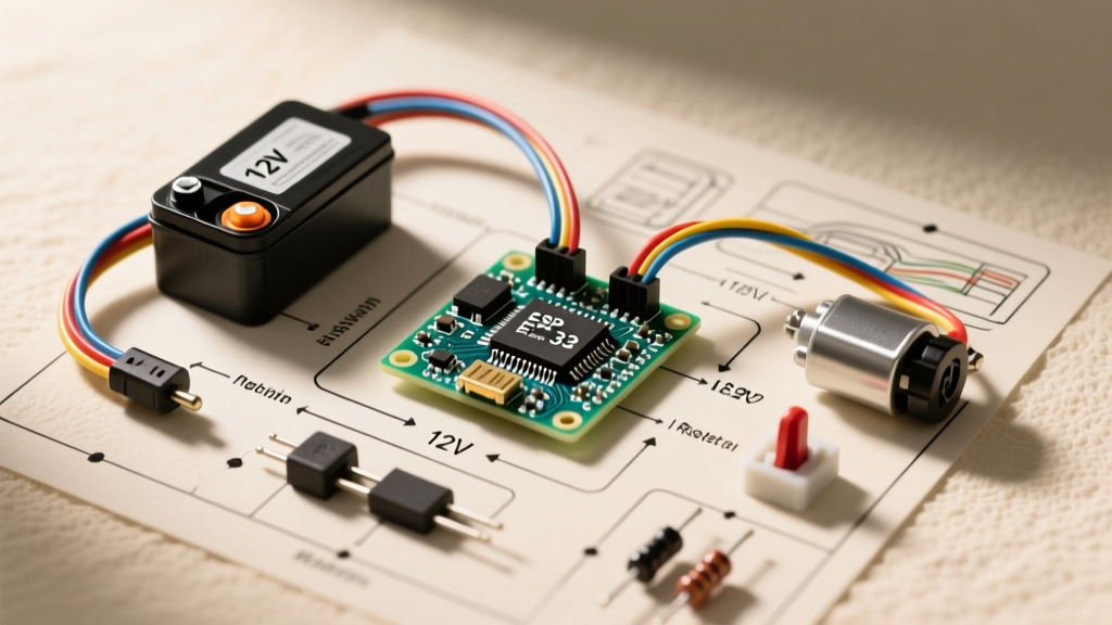

Decoding the 12v Wiring Electric Toy Car Wiring Diagram for Repairs
When a child's ride-on vehicle suddenly stops, parents often face a tangled nest of wires beneath the plastic chassis. Understanding a 12v wiring electric toy car wiring diagram is the fastest way to isolate the fault without resorting to expensive dealership replacements or guesswork. Whether you are working on a Fisher-Price Power Wheels Dune Racer, a Peg Perego Polaris RZR 900, or a generic Kid Trax model, the underlying 12V DC architecture remains remarkably consistent. This guide leverages schematic reading techniques to help you systematically troubleshoot dead motors, unresponsive pedals, and phantom battery drains using a standard digital multimeter.
Anatomy of a Standard 12V Toy Car Circuit
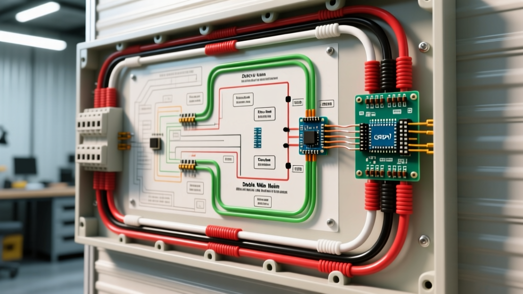
Before probing any wires, you must understand the logical flow of the circuit. A standard 12V ride-on toy utilizes a simple series-parallel configuration. Power originates at a 12-Ah Sealed Lead Acid (SLA) battery, passes through an inline thermal circuit breaker, routes into a Forward/Reverse (F/R) DPDT rocker switch, and finally splits between the foot pedal switch and the drive motors.
Standard Harness Color Codes
While manufacturers occasionally deviate, most 12v wiring electric toy car wiring diagrams adhere to a loose color standard. Use this table as a baseline reference when tracing your specific harness:
| Wire Color | Typical Function | Gauge (AWG) | Multimeter Test Mode |
|---|---|---|---|
| Red | Main +12V Power (Battery to Breaker/Switch) | 14 or 12 AWG | DC Voltage (20V) |
| Black | Main Ground / Motor Return | 14 or 12 AWG | DC Voltage / Continuity |
| White | Forward Motor Feed (from F/R Switch) | 16 AWG | DC Voltage (20V) |
| Yellow / Blue | Reverse Motor Feed / Speed Tap | 16 AWG | DC Voltage (20V) |
| Brown / Orange | High/Low Speed Shifter / Sound Module | 18 AWG | Continuity (Ohms) |
Step-by-Step Troubleshooting Using the Diagram
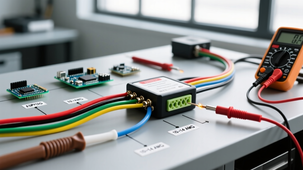
Grab a reliable True RMS multimeter (such as the Fluke 117 or Klein Tools MM400) and follow these schematic-driven diagnostic steps.
Step 1: Battery and Main Harness Verification
A fully charged 12V SLA battery should read between 12.8V and 13.2V at rest. According to Battery University, a reading below 12.4V indicates a state of charge under 75%, which may not provide enough amperage to overcome the static friction of the gearbox.
- Action: Set your multimeter to DC Voltage. Probe the battery terminals directly.
- Load Test: If voltage reads 12.6V, prop the rear wheels off the ground. Press the foot pedal while monitoring the battery terminals. If the voltage instantly collapses below 10.5V, the battery has a failed cell or severe sulfation and must be replaced (e.g., Power Wheels Model 00801-1869, approx. $55).
Step 2: Tracing the Thermal Breaker and F/R Switch
If the battery passes the load test but the car is dead, consult your 12v wiring electric toy car wiring diagram to locate the inline thermal breaker (usually a small black cylinder rated for 30A).
- Probe Point A: Measure voltage on the battery-side of the breaker. It should match battery voltage.
- Probe Point B: Measure voltage on the switch-side of the breaker. If 0V is present here while Point A has 12.8V, the bimetallic strip inside the breaker is fused open or the wire is severed.
- The F/R Switch: The Forward/Reverse switch is a Double Pole Double Throw (DPDT) mechanism. In 'Forward', pins 1 and 3 bridge, sending +12V to the white motor wire. In 'Reverse', the polarity flips. Use the continuity setting on your multimeter to verify internal switch bridging. Carbon buildup on the copper contacts is a frequent failure mode; if continuity is erratic, replace the 6-pin rocker switch (approx. $12).
Step 3: Diagnosing the Foot Pedal and Gearbox
The foot pedal acts as a high-current SPST (Single Pole Single Throw) push-button switch. If you have 12V leaving the F/R switch but the motors do not spin, probe the input terminal of the pedal switch. If voltage is present, press the pedal and probe the output terminal.
Expert Edge Case: If the pedal switch clicks and shows continuity, but the motor remains dead, the fault lies in the motor brushes or the plastic gearbox. Remove the motor and apply 12V directly from a secondary battery. If it spins, the gearbox internal nylon teeth are stripped—a common issue when kids drive off curbs.
Common Failure Modes and Edge Cases
When cross-referencing your physical harness with the 12v wiring electric toy car wiring diagram, watch out for these manufacturer-specific quirks:
- Corroded Spade Connectors: Toy cars are exposed to damp grass and mud. The standard 6.3mm (1/4 inch) spade connectors on the motors often oxidize, creating high resistance. This causes a voltage drop that mimics a dead battery. Fix: Cut off the corroded terminals, strip the wire, and crimp on new nickel-plated female disconnects.
- Phantom Parasitic Draws: Some modern 2025/2026 models include Bluetooth soundboards or LED light kits wired directly to the battery bypassing the main key switch. This will drain a 12-Ah SLA battery in 48 hours. Use the wiring diagram to identify these accessory taps and reroute them through the main ignition switch.
- Thermal Breaker Nuisance Tripping: If the car stops after 30 seconds of driving through thick grass, the 30A breaker is doing its job. The increased amperage draw from the high-friction environment trips the bimetallic strip. Do not bypass the breaker; instead, clear the path or upgrade to a 40A breaker if the wire gauge supports it.
Upgrading the Harness: Wire Gauge Considerations
Many DIYers use the 12v wiring electric toy car wiring diagram as a baseline to upgrade from stock 12V 200W motors to aftermarket 550-size 18A motors. When increasing the amperage draw, the stock 16 AWG motor leads will overheat and melt.
Referencing standard ampacity charts from the Engineering Toolbox, a 16 AWG copper wire in a confined chassis space is safely rated for roughly 10-14 amps. If your upgraded dual-motor setup pulls 25 amps under load, you must rewire the main harness using 12 AWG or 10 AWG silicone-jacketed wire. Silicone wire offers superior heat resistance and flexibility compared to standard PVC, which is critical when routing wires through the tight steering column pivots of a toy car.
Furthermore, if you are upgrading the battery to a 12V Lithium Iron Phosphate (LiFePO4) pack for weight savings and longer runtimes, you must integrate a dedicated Battery Management System (BMS) and a low-voltage disconnect. The Consumer Product Safety Commission (CPSC) strongly advises against using unprotected lithium cells in children's toys due to thermal runaway risks. Always ensure your BMS includes over-current and short-circuit protection tailored to the toy's 30A peak draw.
Frequently Asked Questions
Why does my toy car only go in reverse but not forward?
This is almost always a failure within the Forward/Reverse DPDT switch. Consult the 12v wiring electric toy car wiring diagram to locate the 'Forward' bridging pins. Use a multimeter to test for continuity across those specific pins when the switch is toggled forward. If the circuit is open, the internal copper rocker is broken or heavily oxidized. Replace the switch.
Can I wire two 12V batteries in series to make the car faster?
Wiring two 12V batteries in series creates a 24V system. While this will double the speed, it will instantly fry the stock 12V motors, melt the 16 AWG wiring harness, and likely cause the foot pedal switch to arc and catch fire. If you want 24V, you must follow a dedicated 24V conversion diagram, which requires upgrading all main harness wires to 10 AWG, installing 24V-rated contactors instead of the plastic pedal switch, and swapping to 24V gearboxes.
How do I test a motor without a multimeter?
You can bypass the entire 12v wiring electric toy car wiring diagram by taking a pair of jumper wires connected directly to a known-good 12V battery. Touch the jumper wires directly to the two metal spade terminals on the motor. If the motor spins, the motor is healthy, and the fault lies in the switches or harness. If it sparks but does not spin, the motor brushes are worn out or the armature is seized.