
The Core Anatomy of a Direct-On-Line (DOL) Starter
When industrial facilities need to run 3-phase AC induction motors across the line, the Direct-On-Line (DOL) starter remains the undisputed workhorse. Unlike Variable Frequency Drives (VFDs) or soft starters that ramp up voltage, a DOL starter applies full line voltage to the motor terminals instantly. As of 2026, despite the rise of smart motor controllers, DOL starters account for over 60% of all sub-15HP motor control applications due to their rugged simplicity, low cost, and ease of maintenance.
To master electric motor starter wiring, you must first understand that a 'starter' is not a single component. It is an assembly of two critical devices:
- The Magnetic Contactor: An electrically controlled switch that uses an electromagnetic coil to close heavy-duty main power contacts. It also includes auxiliary contacts (typically 13-14 for Normally Open) used for control circuit logic.
- The Thermal Overload Relay: A protective device mounted directly beneath the contactor. It monitors the current drawn by the motor and trips a mechanical linkage to open the contactor if the current exceeds the motor's Full Load Amps (FLA) for a sustained period, preventing insulation burnout.
Sizing Your Contactor and Overload Relay
Incorrect sizing is the leading cause of premature contactor failure and nuisance tripping. According to the NFPA 70 (National Electrical Code) Article 430, motor branch circuits and controllers must be sized based on the motor's FLA and specific service factors. Utilization categories matter: AC-3 rating is required for standard squirrel-cage motor starting.
Below is a real-world sizing matrix using the industry-standard Schneider Electric TeSys D series, reflecting current 2026 market availability and pricing.
| Motor HP (460V 3-Phase) | Approx. FLA | Contactor Model (AC-3) | Contactor Cost (2026) | Overload Relay Model | Overload Amp Range |
|---|---|---|---|---|---|
| 3 HP | 4.8A | LC1D09 (9A) | $85 - $100 | LRD12 | 5.5A - 8A |
| 5 HP | 7.6A | LC1D09 (9A) | $85 - $100 | LRD14 | 7A - 10A |
| 7.5 HP | 11A | LC1D18 (18A) | $95 - $115 | LRD16 | 9A - 13A |
| 10 HP | 14A | LC1D18 (18A) | $95 - $115 | LRD21 | 12A - 18A |
| 15 HP | 21A | LC1D25 (25A) | $110 - $135 | LRD22 | 16A - 24A |
Pro Tip: Always set the overload relay dial exactly to the motor nameplate FLA, not the breaker size. If the motor is in a high-ambient environment (above 40°C / 104°F), you must derate the overload or select a higher frame size to prevent nuisance thermal trips.
Power Circuit Wiring: Routing the High Voltage
The power circuit carries the high-current 3-phase load from the disconnect switch to the motor. For a 10 HP motor at 460V (approx. 14A FLA), 12 AWG THHN copper wire is the minimum required by code, but most industrial panels standardize on 10 AWG for mechanical robustness and voltage drop mitigation.
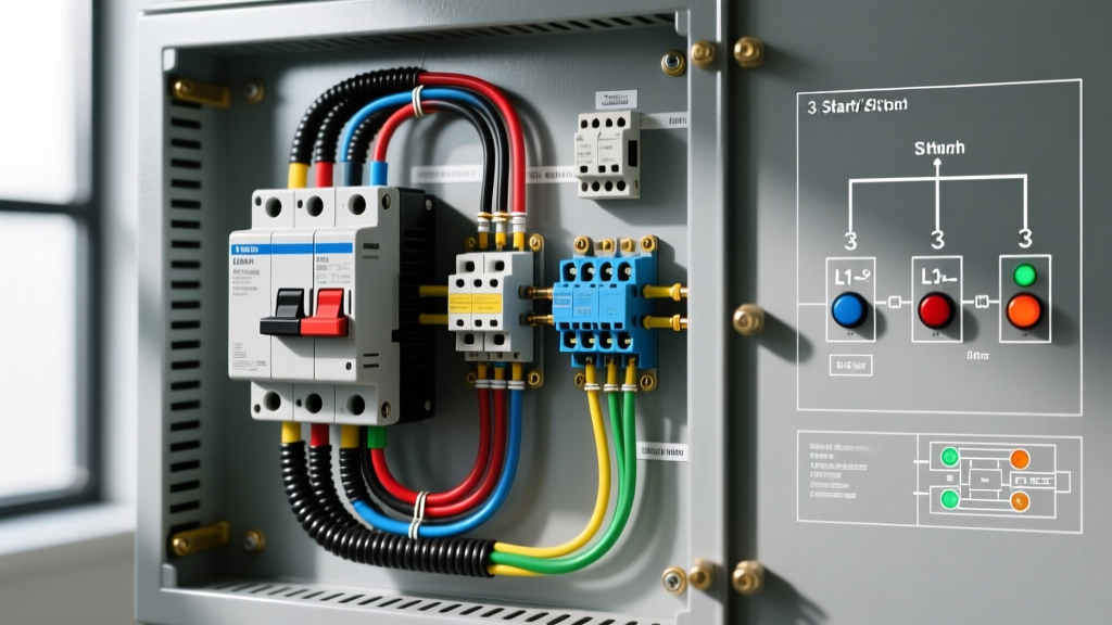
- Line Side (L1, L2, L3): Route your 3-phase supply lines from the fuses or motor-rated circuit breaker into the top terminals of the contactor (marked 1/L1, 3/L2, 5/L3).
- Load Side (T1, T2, T3): Route jumper wires from the bottom of the contactor (2/T1, 4/T2, 6/T3) directly into the top input terminals of the thermal overload relay.
- Motor Feed: Route the final set of power conductors from the bottom of the overload relay to the motor terminal peckerhead.
Critical Torque Specs: Hand-tightening terminals is a primary cause of arc faults and phase loss. For standard M3.5 terminal screws on a TeSys D contactor, use a calibrated torque screwdriver set to 1.2 Nm to 1.5 Nm (10.6 to 13.3 lb-in). Under-torqued connections increase resistance, generating heat that tricks the thermal overload into tripping prematurely.
The 3-Wire Control Circuit: Start, Stop, and Seal-In
The control circuit dictates how the contactor coil is energized. A standard 3-wire control provides low-voltage release protection—meaning if power fails, the motor will not automatically restart when power returns, protecting operators from unexpected machinery startup.
Wiring the Pushbuttons and Holding Contact
- Stop Circuit: Wire the control voltage hot leg (e.g., 120VAC or 24VDC) to the Normally Closed (NC) terminal of the STOP pushbutton. Run a wire from the NC output to the Normally Open (NO) terminal of the START pushbutton.
- Start Circuit: Wire the NO output of the START button to the A1 terminal of the contactor coil.
- The Seal-In (Holding) Circuit: This is the magic of electric motor starter wiring. Wire a jumper from the NO input of the START button to terminal 13 of the contactor's auxiliary block. Wire another jumper from the auxiliary NO output terminal 14 directly to the coil's A1 terminal.
- Overload Integration: Wire the A2 terminal of the coil to the NC terminal of the overload relay (usually marked 95). Wire the overload's 96 terminal back to the control circuit neutral or ground reference.
When you press START, the coil energizes. The main contacts close, and simultaneously, the 13-14 auxiliary contact closes. When you release the START button, the 13-14 auxiliary contact maintains the current path to A1, 'sealing in' the circuit. Pressing STOP breaks the circuit, dropping the coil and opening all contacts.
Control Voltage Selection: 120VAC vs. 24VDC in 2026
Historically, 120VAC control circuits derived from a step-down transformer were the norm. However, modern industrial standards heavily favor 24VDC control circuits. Why? Safety and integration. A 24VDC control circuit eliminates the risk of lethal shock at the pushbutton station. Furthermore, if you plan to integrate the starter with a modern PLC (Programmable Logic Controller), 24VDC transistor outputs can directly drive the contactor coil (or an interposing relay) without requiring bulky mechanical relays or AC switching modules. Expect to pay roughly $45 for a high-quality 24VDC coil (e.g., Schneider LX1D) compared to $25 for a 120VAC coil.
Real-World Failure Modes and Edge Case Troubleshooting
Even perfectly wired DOL starters experience faults. Here is how to diagnose the most common edge cases using industry-standard methodologies.
1. Contactor Chattering (Humming and Vibrating)
If the contactor rapidly opens and closes or emits a loud 60Hz hum, the magnetic field is insufficient to hold the armature closed. According to Fluke's electrical troubleshooting guidelines, AC coils require at least 85% of their rated voltage to seal in reliably. Use a true-RMS multimeter to measure the voltage directly across A1 and A2 while the coil is energized. If you read 95V on a 120V coil, you have excessive voltage drop in the control wiring or an undersized control transformer. Additionally, check the contactor's magnetic face for rust, oil, or debris, which creates an air gap and causes severe chattering.
2. Nuisance Thermal Tripping
If the overload relay trips but the motor feels cool to the touch, check the trip class. Standard overloads are Class 10 (trips in 10 seconds at 6x FLA). If you are starting a high-inertia load like a large fan or crusher, the extended acceleration time will trick a Class 10 relay. Swap to a Class 20 overload relay or an electronic solid-state overload (like the TeSys Giga series) which allows for programmable trip curves. Also, verify that the overload's ambient temperature compensation dial hasn't been bumped during installation.
3. Single-Phasing and Phase Loss
Single-phasing occurs when one of the three power legs is lost (e.g., a blown fuse on L2). The motor will attempt to continue running on the remaining two phases, drawing up to 173% of its normal FLA, rapidly destroying the stator windings. Standard bimetallic overload relays feature a differential trip mechanism to detect this imbalance. If you are wiring in an area with frequent utility phase loss, upgrade to a solid-state overload relay with dedicated phase-loss and phase-reversal protection, as recommended by NEMA MG-1 standards for motor protection in unstable grids.
Final Safety and Commissioning Checklist
Before applying 460V power to your newly wired electric motor starter, complete this mandatory verification sequence:
- Megger Test: Use an insulation resistance tester at 500VDC to verify >1 Megohm resistance between all motor phases and ground.
- Bump Test: Disconnect the motor load. Energize the control circuit and 'bump' the start button to verify the contactor pulls in smoothly and the auxiliary seal-in holds.
- Rotation Check: Reconnect the motor. Start the motor and immediately stop it to verify correct shaft rotation. If reversed, swap any two of the three main power legs (e.g., swap T1 and T2).
- LOTO Integration: Ensure the upstream disconnect switch is fully integrated with your facility's Lockout/Tagout procedures, featuring a padlockable handle in the OFF position.
Proper electric motor starter wiring is a blend of strict code adherence, precise mechanical torque, and logical control circuit design. By selecting the correct NEMA or IEC components and following these 3-phase DOL protocols, you ensure decades of reliable, safe motor operation.