
The Hidden Fire Hazard in Aftermarket Lighting
Every year, off-road vehicles and commercial trucks suffer catastrophic electrical fires due to improper auxiliary lighting installations. The root cause is almost always a failure to follow established electrical codes when executing a wiring diagram for LED light bar with switch configurations. Most budget-friendly light bar kits sold online include substandard 18-gauge zip cord, fragile inline glass fuses, and non-waterproof connectors. When these components are subjected to the harsh under-hood environment of a modern vehicle, the insulation melts, the wire shorts to the chassis, and a fire ignites before the factory fuse box can react.
As a senior electrical technician, I approach every auxiliary lighting project through the lens of the SAE J1128 Low Tension Primary Cable standard and general fire safety principles outlined by the NFPA electrical safety codes. This guide provides a rigorous, code-compliant blueprint for wiring a high-draw LED light bar safely, utilizing automotive-grade relays, correct wire gauges, and proper fuse placement.
SAE-Compliant Bill of Materials (BOM)
Before touching a wire stripper, you must source the correct materials. Standard household THHN wire or basic PVC hook-up wire will become brittle and crack under hood temperatures that routinely exceed 180°F (82°C) in 2026 turbo-diesel and high-compression gas engines.
| Component | Specification / Standard | Recommended Product / Type | Est. Cost (2026) |
|---|---|---|---|
| Main Power Wire | 12 AWG SXL (Cross-Linked Polyethylene) | SAE J1128 compliant, 105°C rated | $1.20 / ft |
| Trigger/Switch Wire | 16 AWG GXL or SXL | Stranded copper, thin-wall insulation | $0.85 / ft |
| Relay | ISO Mini 4-Pin, 40A rating | Littelfuse 75 Series or Bosch JD1914 | $8.50 |
| Overcurrent Protection | 20A Mini-Blade (ATM) Fuse & Holder | Littelfuse ATOF/Mini waterproof holder | $12.00 |
| Switch | IP67/IP68 Rated Rocker | Carling V-Series or Nilight Marine | $15.00 |
| Connectors | Adhesive-Lined Heat Shrink Crimps | 3M Highland or Ancor Marine | $18.00 / box |
Circuit Architecture: The 4-Pin Relay Logic
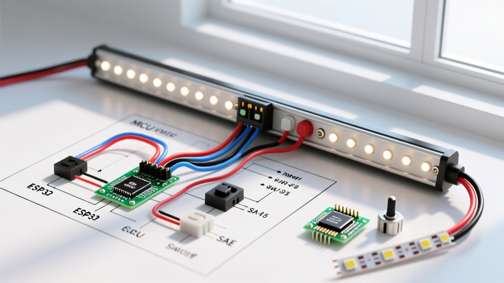
A code-compliant wiring diagram for LED light bar with switch setups never routes the full amperage of the light bar through the dashboard switch. A 50-inch dual-row LED bar typically draws between 12A and 16A at 14.4V (engine running). Running this current through a standard dashboard rocker switch will melt the switch contacts within weeks. Instead, we use a relay as a high-current remote switch.
Understanding the ISO Mini Relay Pins
- Pin 30 (Common): High-current 12V+ input directly from the battery (via the main fuse).
- Pin 87 (Normally Open): High-current 12V+ output to the LED light bar positive terminal.
- Pin 86 (Coil Positive): Low-current 12V+ trigger input from the dashboard switch.
- Pin 85 (Coil Ground): Low-current ground for the relay coil, tied to a clean chassis ground.
Expert Insight: According to Littelfuse automotive relay application guidelines, you must always ensure the relay coil circuit is protected by its own low-amperage fuse (typically 3A to 5A) if it is tapped directly into a factory ignition circuit. If running a dedicated switch to a fused battery source, the main inline fuse protects the entire system.
Step-by-Step Code-Compliant Installation Flow
Follow this exact sequence to ensure maximum safety and compliance with automotive electrical best practices.
Phase 1: High-Current Power Routing
- Disconnect the Battery: Always isolate the negative terminal first to prevent accidental short circuits while working near the positive terminal.
- Install the Main Fuse: Crimp a ring terminal to one end of your 12 AWG SXL wire and attach it to the battery positive. Critical Safety Rule: The 20A Mini-Blade fuse holder must be installed within 18 inches of the battery terminal. This ensures that if the main power wire chafes against the chassis, the circuit is protected before the short can reach the battery and cause a fire.
- Route to the Relay: Run the fused 12 AWG wire through the firewall or grille to the relay mounting location. Secure it with UV-resistant split loom and adhesive-backed zip ties every 12 inches.
- Terminate at Pin 30: Crimp a female quick-disconnect terminal onto the wire and push it securely onto Relay Pin 30.
- Run Power to the Light Bar: Connect a new length of 12 AWG wire to Relay Pin 87 and route it to the positive terminal of the LED light bar.
- Ground the Light Bar: Connect the light bar negative wire to a clean, bare-metal point on the chassis using a star washer to bite through paint and prevent voltage drop.
Phase 2: Low-Current Trigger Circuit
- Switch Power Source: Run 16 AWG wire from an ignition-switched 12V source (e.g., windshield wiper fuse tap or auxiliary upfitter switch) to the dashboard switch input terminal.
- Switch Output to Relay: Run 16 AWG wire from the switch output terminal through the firewall to Relay Pin 86.
- Ground the Relay Coil: Attach 16 AWG wire to Relay Pin 85 and terminate it to a local chassis ground near the relay.
Advanced Edge Cases & Troubleshooting
Modern vehicles present unique electrical challenges that older wiring diagrams fail to address. Here is how to handle the most common edge cases in 2026 vehicle platforms.
The CAN-Bus Inductive Kickback Problem
If you are triggering the relay coil (Pin 86) using a factory upfitter switch controlled by the vehicle's CAN-bus or Body Control Module (BCM), the inductive spike generated when the relay coil de-energizes can feed back into the BCM. This 'flyback voltage' can permanently fry a $1,200 control module or trigger a Check Engine Light (CEL).
The Solution: Solder a 1N4001 flyback diode across the relay coil pins (85 and 86). The silver stripe on the diode must point toward Pin 86 (the positive trigger side). This creates a recirculation loop that safely dissipates the inductive spike.
Voltage Drop and Dimming Issues
If your LED light bar flickers or operates at 80% brightness, you are experiencing severe voltage drop. A 50-inch bar drawing 15A over 15 feet of wire requires precise gauge calculations.
- Acceptable Drop: Automotive lighting circuits should not exceed a 3% voltage drop (approx. 0.4V on a 14.4V system).
- The Fix: If you used 14 AWG wire for a run longer than 10 feet, upgrade to 12 AWG or even 10 AWG SXL wire. Furthermore, ensure your chassis ground is not relying on a painted bolt; use a dedicated negative bus bar tied directly to the battery negative if the chassis ground is compromised by rust or bed-liner overspray.
Final Inspection & Weatherproofing
Code compliance does not end at the electrical connections; it extends to environmental protection. All under-hood crimps must be sealed with adhesive-lined heat shrink. When heated, the inner adhesive melts and flows into the wire strands, creating a watertight seal that prevents capillary action from wicking moisture into the copper strands. Finally, mount the relay in a vertical orientation with the pins pointing downward. This prevents water from pooling inside the connector housing and causing galvanic corrosion between the copper terminals and the brass relay pins.
By adhering to this rigorous wiring diagram for LED light bar with switch methodology, you ensure your auxiliary lighting system is not only brilliantly illuminated but fundamentally safe, reliable, and compliant with the highest automotive electrical standards.