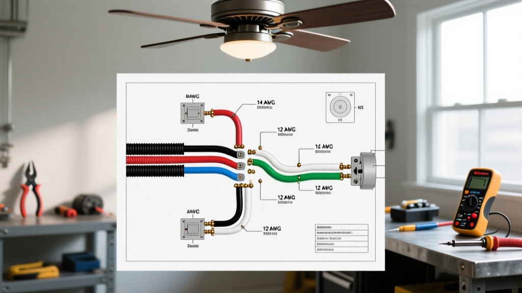

Decoding the Wiring Diagram for Hunter Ceiling Fan With Light Setups
Installing a ceiling fan with an integrated light kit requires more than just matching colors; it demands a strict adherence to wire gauge limitations and an understanding of manufacturer-specific color deviations. When searching for a wiring diagram for Hunter ceiling fan with light configurations, electricians and DIYers frequently encounter a unique color mapping that differs from standard appliance wiring. Hunter Fan Company utilizes a proprietary color code for their light kit leads, which, if miswired, can result in blown capacitors, fried LED drivers, or severe fire hazards.
This comprehensive reference guide breaks down the exact wire gauge requirements, National Electrical Code (NEC) compliance standards, and the specific color-to-color translation matrix required for modern Hunter models, including the Builder Elite, Original, and Symphony smart fan series.
Hunter to House Wire Color Code Translation Matrix
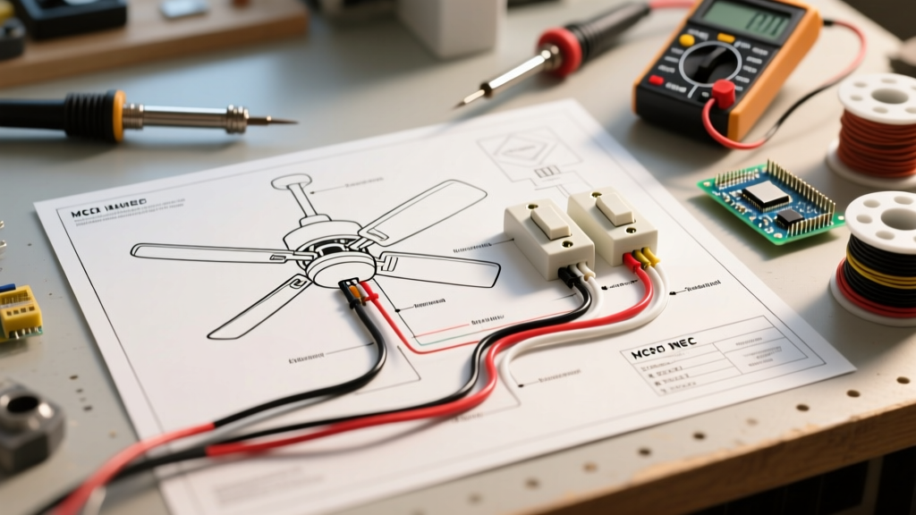
Standard residential NM-B (Romex) cable follows a strict black-white-bare color convention for 2-wire setups, and adds a red conductor for 3-wire dual-switch setups. Hunter ceiling fans, however, introduce a blue wire into the canopy. Below is the definitive translation matrix for a standard dual-switch wall configuration (one switch for the fan motor, one for the light kit).
| House NM-B Wire (Ceiling Box) | Hunter Fan Wire (Canopy) | Function & Destination | NEC / Safety Notes |
|---|---|---|---|
| Black (Always Hot) | Black | Fan Motor Power | Connects to Switch Leg 1 |
| Red (Switched Hot) | Blue | Light Kit Power | Connects to Switch Leg 2 (Hunter specific) |
| White (Neutral) | White (x2 or x3) | Shared Neutral Return | Must include LED driver neutral if applicable |
| Bare Copper / Green | Green | Equipment Grounding | Must bond to metal ceiling junction box |
CRITICAL WARNING: Never connect the Hunter Blue wire to the house White (neutral) wire. Doing so will create a dead short the moment the wall switch is toggled, instantly tripping the breaker and potentially destroying the fan's internal light limiter or LED driver.
Wire Gauge Engineering & NEC Compliance
Selecting the correct wire gauge is paramount for ceiling fan installations. The NEC dictates branch circuit sizing based on the overcurrent protection device (breaker) and the continuous load of the appliance.
Branch Circuit vs. Appliance Tap Conductors
A common point of confusion arises when opening the Hunter fan canopy and discovering that the internal lead wires (the pigtails exiting the motor housing) are often 18 AWG or 16 AWG TEW (Thermoplastic Equipment Wire). Homeowners frequently ask if they must step down their house wiring to match. The answer is no.
According to the National Fire Protection Association (NFPA) NEC Article 240.4, branch circuit conductors must be protected at their ampacity. However, appliance internal wiring is governed by UL 507 (Standard for Motor-Operated Appliances), which allows smaller gauge tap conductors within the appliance housing because the physical length is under 18 inches and the overcurrent protection (the breaker) is protecting the branch circuit, not the internal tap.
Gauge Selection Chart for Hunter Fans
| Breaker Size | Minimum House Wire Gauge (NM-B) | Max Allowable Load | Hunter Fan Compatibility |
|---|---|---|---|
| 15 Amp | 14 AWG | 1,800 Watts | Ideal for dedicated fan/light circuits |
| 20 Amp | 12 AWG | 2,400 Watts | Required for shared bedroom/bathroom circuits |
| 30+ Amp | 10 AWG or lower | N/A | DO NOT USE (Violates NEC 240.4(D)) |
Load Calculation Context: A high-torque Hunter WhisperWind motor draws approximately 0.65 Amps (78 Watts) on high speed. An integrated 4-bulb LED light kit draws roughly 36 Watts (0.3 Amps). The combined maximum load is under 1.5 Amps. Therefore, a 14 AWG wire on a 15A breaker is more than sufficient, provided the circuit is not overloaded by other high-draw devices like space heaters or vacuum cleaners.
Integrating the Hunter Universal Remote Receiver
If your installation utilizes a Hunter Universal Remote Control Kit (such as model 85112 or 99119), the wiring diagram shifts from the ceiling canopy to the remote receiver module, which sits inside the fan's mounting bracket.
Receiver Wiring Sequence
- House to Receiver: Connect House Black to Receiver Black. Connect House White to Receiver White. Connect House Ground to Receiver Ground (if equipped, otherwise bond to box).
- Receiver to Fan Motor: Connect Receiver Blue to Fan Black (Motor).
- Receiver to Light Kit: Connect Receiver White (Light) to Fan Blue (Light).
- Neutral Completion: Connect Receiver White (Neutral) to Fan White.
Note: When using a remote receiver, the wall switch must remain in the 'ON' (closed) position at all times to provide continuous 120V power to the receiver's logic board. Using a standard toggle switch to cut power will reset the remote pairing and degrade the receiver's internal capacitors over time.
Smart Fan Edge Cases: Hunter Symphony & Signal Models
Modern Wi-Fi and Zigbee-enabled Hunter fans (like the Symphony and Signal lines) introduce a massive hurdle for older homes: the requirement for a neutral wire at the wall switch box.
Unlike standard mechanical switches, smart wall controls (like the Hunter 99370) contain internal radios that require a complete 120V circuit to remain connected to your network. If your home was built before 2011 and utilizes a 'switch loop' (where only a black and white wire run from the ceiling to the switch, with the white acting as a hot), you cannot install a Hunter smart wall control without pulling new 14/3 or 12/3 NM-B cable.
For homes lacking a switch-box neutral, the only compliant workaround is to bypass the wall switch entirely (wire-nut the hots together in the switch box) and rely exclusively on the Hunter SimpleConnect app or a battery-operated RF remote for control.
Common Failure Modes & Troubleshooting
Even with the correct wiring diagram for Hunter ceiling fan with light setups, specific edge cases can cause operational failures. Reference these diagnostics before assuming a motor defect:
- Flickering LED Light Kit: Often caused by using an incompatible dimmer switch on the red (light) wire. Hunter integrated LED drivers require ELV (Electronic Low Voltage) or specific CL (C-L) dimmers. Standard TRIAC incandescent dimmers will cause strobing and eventually burn out the driver.
- Motor Humming Without Rotation: Indicates a failed run capacitor. Hunter typically uses a 4.5µF or 5µF / 250V AC capacitor located in the switch cup. This is a $6 replacement part, not a dead motor.
- Breaker Trips When Light is Turned On: Usually a pinched Blue wire in the canopy. The metal canopy cover can easily slice the 18 AWG Blue wire insulation if not dressed carefully, causing a ground fault against the metal housing.
Final Safety & Mounting Verification
Electrical connections are only half the battle. The U.S. Department of Energy emphasizes that ceiling fans must be mounted to junction boxes specifically rated for fan support (marked 'Acceptable for Fan Support'). Standard drywall anchor boxes will fail under the dynamic vibrational load of a 20 lb Hunter fan, leading to catastrophic detachment. Always verify the UL-listed rating stamped inside the plastic or metal junction box before making your first wire connection.
For exact torque specifications and model-specific canopy dressing instructions, always cross-reference your physical unit with the official Hunter Fan Company Installation Manuals database, as internal wire routing clips vary significantly between the Original cast-iron models and the modern stamped-steel Builder series.