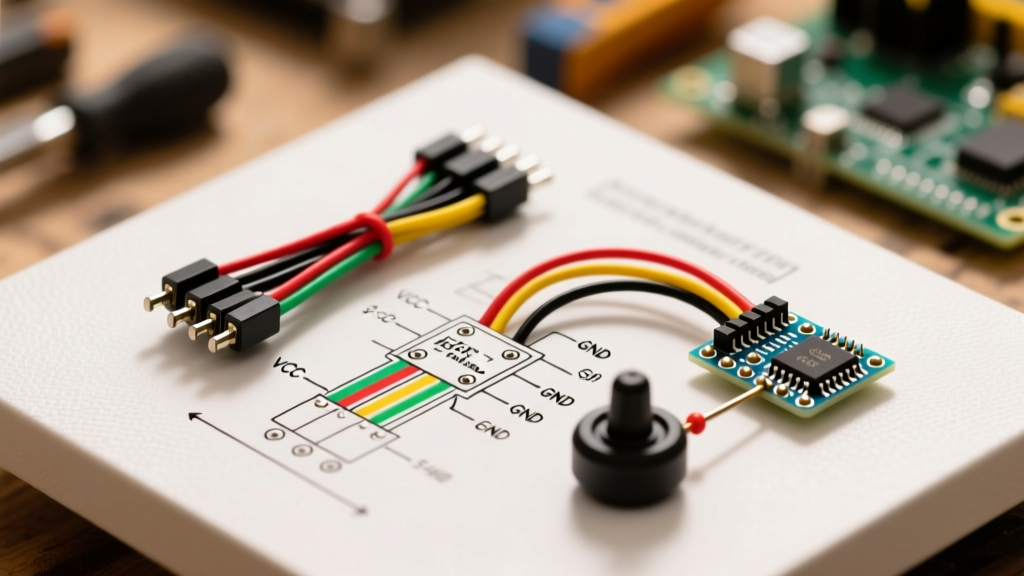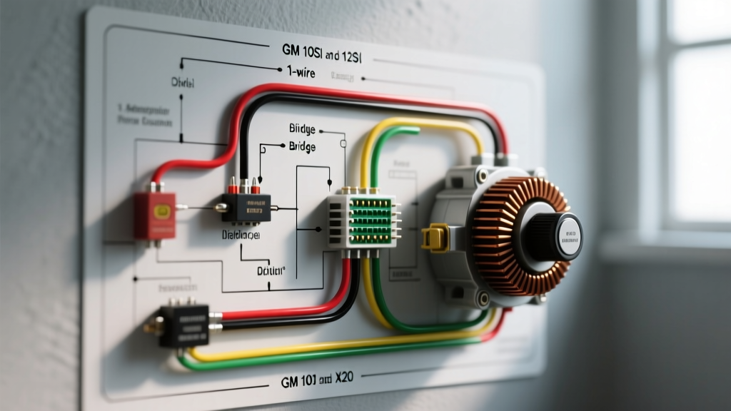

Why the GM Delco 10SI and 12SI Dominate Vehicle Swaps
When executing an LS engine swap, restoring a classic GM truck, or building a high-draw restomod, understanding the wiring diagram for an alternator is the difference between a reliable charging system and a stranded vehicle. The General Motors Delco Remy 10SI and 12SI alternators remain the undisputed champions of the DIY automotive world. Their internal voltage regulators, robust diode trios, and standardized 3-pin plug configurations make them universally adaptable.
However, as of 2026, the electrical demands of modern vehicle builds have shifted dramatically. While a stock 1978 C10 might have been perfectly happy with a 63-amp 10SI alternator, today's restomods running Holley Terminator X EFI systems, dual electric cooling fans, and high-wattage LED lighting arrays require a minimum of 100 to 145 amps. This necessitates a deep understanding of the 12SI platform and high-output aftermarket variants like the Powermaster 17294 or the Remy 712-7120. Remanufactured 10SI units typically cost between $65 and $85, while high-output 12SI models range from $110 to $250 depending on the winding specifications.
Decoding the Alternator Plug: Terminal Anatomy
To properly read a wiring diagram for an alternator of this generation, you must understand the physical terminals. The Delco 10SI and 12SI feature a prominent BAT (Battery) stud on the rear housing and a rectangular 3-pin connector on the side. Crucially, only two of the three pins are used.
- BAT Terminal: The main high-current output post. This connects directly to the vehicle's battery positive terminal or the main distribution busbar.
- Terminal #1 (Exciter/Field/Lamp): This terminal provides the initial 'excitation' voltage required to turn the alternator on. It is typically routed through an ignition-switched source or an instrument cluster indicator lamp.
- Terminal #2 (Voltage Sense): The internal voltage regulator uses this terminal to read the actual voltage at the battery. This allows the regulator to compensate for voltage drop across the main charge wire.
The Great Debate: 1-Wire vs. 3-Wire Configurations
When sourcing a wiring diagram for an alternator, you will inevitably encounter the '1-wire' versus '3-wire' debate. Both configurations utilize the exact same internal voltage regulator, but they handle the excitation and sensing circuits differently.
The 1-Wire Setup (The Lazy Mechanic's Friend)
A 1-wire alternator features an internal jumper wire connecting the BAT terminal directly to Terminal #1 and Terminal #2. You only need to run a single heavy-gauge wire from the alternator BAT post to the battery.
Expert Warning: The primary drawback of a 1-wire setup is the 'exciter threshold.' Because the regulator senses voltage directly at the alternator housing, the engine often must be revved to 1,500–2,000 RPM upon initial startup to 'wake up' the alternator and begin charging. Furthermore, it cannot compensate for voltage drop in the main charge cable, potentially leading to undercharged batteries in high-draw scenarios.
The 3-Wire Setup (The OEM Standard)
The 3-wire configuration is vastly superior for modern, high-amperage builds. By separating the exciter and sense circuits, you allow the alternator to turn on immediately at idle and accurately monitor battery voltage regardless of voltage drop in the main power cable.
- Main Charge Wire: Runs from the BAT terminal to the battery positive post (or starter solenoid battery lug).
- Exciter Wire (Terminal #1): Runs to an ignition-switched 12V source. If your vehicle has a factory 'GEN' or 'ALT' idiot light, routing this wire through the bulb provides the necessary initial resistance and excitation voltage.
- Sense Wire (Terminal #2): Runs directly to the battery positive terminal or the main fuse block positive busbar. This wire carries virtually zero current, so a small 16 AWG wire is sufficient.
Wire Gauge Selection: Preventing Voltage Drop
The most common mistake when following a wiring diagram for an alternator is undersizing the main BAT charge wire. According to the SAE J1128 standard for low-tension primary automotive cable, wire gauge must be selected based on both maximum amperage and the total length of the wire run (including the ground path).
| Alternator Output | Recommended Wire Gauge (Under 4 ft) | Recommended Wire Gauge (4 ft to 8 ft) | Maximum Fuse / MegaFuse Rating |
|---|---|---|---|
| 63A - 80A (10SI) | 10 AWG | 8 AWG | 100 Amp |
| 94A - 110A (12SI) | 8 AWG | 6 AWG | 125 Amp |
| 120A - 145A (High Output) | 6 AWG | 4 AWG | 150 Amp |
Note: Always install a high-amperage fuse or MegaFuse within 18 inches of the battery connection on the main charge wire to prevent catastrophic electrical fires in the event of a short circuit.
Real-World Failure Modes and Edge Cases
Even with a perfect wiring diagram for an alternator, improper execution leads to specific, diagnosable failure modes. Here are the most frequent issues we see in the shop:
1. The 'Jumpered Sense' Mistake
Many DIYers build a 3-wire harness but get lazy and jumper Terminal #2 directly to the alternator's BAT post instead of running a dedicated wire to the battery. This defeats the purpose of the 3-wire system. If your main charge wire has a 0.5V drop under heavy load, the regulator will sense 14.2V at the BAT post and stop charging, while the actual battery is only receiving 13.7V. Over time, this leads to chronic battery sulfation.
2. Alternator Whine in the Audio System
High-output alternators (especially those with 6-phase hairpin stators) can introduce severe alternator whine into aftermarket audio systems. This is rarely an alternator defect; it is a grounding issue. The alternator case must have a pristine, bare-metal connection to the engine block, and the engine block must have a minimum 2 AWG ground strap connecting it to the vehicle chassis and the negative battery terminal.
3. Exciter Wire Backfeed
If you wire Terminal #1 to a standard 12V ignition source without using a diode or an incandescent indicator lamp, the alternator can backfeed voltage into the ignition circuit. This results in the engine continuing to run (dieseling) after the ignition key is turned off. Always use a 1-Amp inline diode on the exciter wire if bypassing the factory dash light.
Diagnostic Procedure: The Voltage Drop Test
To verify your wiring diagram for an alternator was executed correctly, perform a voltage drop test. As outlined by AA1Car charging system diagnostics, this test is far more accurate than simply measuring battery voltage.
- Set your digital multimeter to DC Volts.
- Start the engine and turn on all major electrical loads (headlights on high beam, HVAC blower on max, rear defroster on).
- Rev the engine to 2,000 RPM.
- Place the Red multimeter probe directly on the alternator BAT terminal.
- Place the Black multimeter probe directly on the battery positive post.
- Read the voltage. A reading of 0.2V or less indicates a healthy circuit. A reading above 0.5V indicates excessive resistance, requiring you to upgrade your wire gauge or clean your terminal crimps.
Expert FAQ
Can I use a 12SI plug on a 10SI alternator?
Yes. The physical plastic connector and pin spacing are identical across the Delco 10SI, 12SI, and even the later 15SI and 17SI models. You can use the same pre-made pigtail harness for any of these internally regulated SI-series alternators.
Why does my 1-wire alternator not charge until I rev the engine?
This is an inherent design characteristic of 1-wire setups. The internal regulator requires a specific voltage differential between the BAT terminal and the internal sense circuit to 'turn on' the rotor field. Revving the engine increases the residual magnetism voltage, crossing the threshold and exciting the field. If this behavior is unacceptable for your build, convert to a 3-wire configuration.
Do I need a smaller pulley for a high-output alternator?
If you have upgraded from a stock 63A 10SI to a 145A high-output alternator for a restomod build, the larger internal stator requires more rotational force. If you experience belt slip or squealing at idle, installing a smaller alternator pulley (e.g., stepping down from 2.5 inches to 2.2 inches) will increase the rotor RPM, improving low-speed charging output. Ensure you use a high-grip serpentine belt like the Gates FleetRunner.