
The Evolution of Heat Pump Wiring in 2026
As heat pumps continue to dominate the residential and light-commercial HVAC market, understanding the specific electrical requirements of these systems is more critical than ever. According to the U.S. Department of Energy, modern cold-climate heat pumps can operate efficiently at temperatures well below zero, but this advanced performance relies heavily on flawless electrical integration. A standard wiring diagram for heat pump installations is not just a suggestion; it is a strict roadmap that bridges high-voltage power distribution with low-voltage logic controls. Misinterpreting this diagram can lead to catastrophic compressor failure, nuisance breaker tripping, or complete system malfunction. This tutorial breaks down the anatomy of heat pump wiring, from the main disconnect to the 24V thermostat terminals, ensuring your 2026 installations are safe, code-compliant, and optimized for peak efficiency.
Anatomy of a Heat Pump Wiring Diagram
Unlike a standard air conditioner, a heat pump requires bidirectional refrigerant flow and complex defrost logic. When you pull the schematic from the inside of the outdoor condenser panel door, you will notice three distinct electrical circuits:
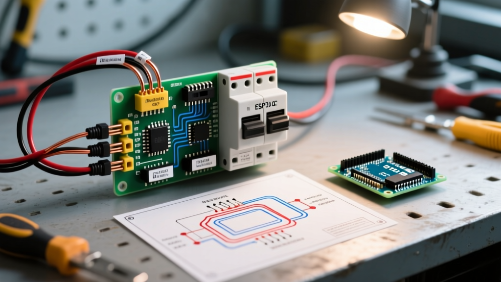
- High-Voltage Power Circuit: Feeds 208/240V single-phase power from the main electrical panel to the outdoor unit and the indoor air handler.
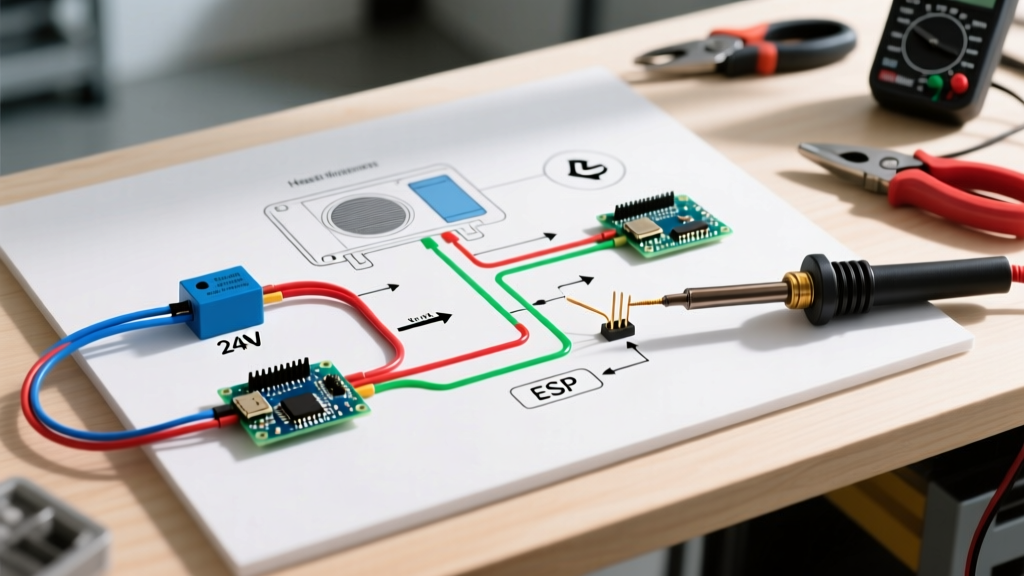
- Control Circuit (24V): Steps down the voltage via a transformer in the air handler to send logic signals to the outdoor contactor, reversing valve, and defrost board.
- Communication Bus (Modern Systems): High-efficiency variable-speed models use a proprietary digital bus rather than traditional analog 24V signals.
Safety Warning: Always perform Lockout/Tagout (LOTO) procedures before opening any panel. Heat pumps store lethal voltage in the run capacitors and inverter boards. Wait at least 10 minutes after disconnecting power for inverter capacitors to discharge, and verify zero voltage with a CAT III or CAT IV multimeter.
High-Voltage Sizing and NEC Compliance
The high-voltage side of the wiring diagram for heat pump setups dictates the wire gauge, breaker size, and disconnect ratings. Sizing must be based on the Minimum Circuit Ampacity (MCA) and Maximum Overcurrent Protection (MOCP) listed on the unit data plate, not just the tonnage. Furthermore, the NFPA 70 National Electrical Code (NEC) mandates strict GFCI protection rules for outdoor HVAC equipment, which has caused significant nuisance tripping issues in the field if not wired with properly shielded cables and isolated grounds.
| System Tonnage | Typical MCA | Max Breaker (MOCP) | Copper Wire Gauge (THHN/THWN-2) | Disconnect Rating |
|---|---|---|---|---|
| 2.0 Ton | 14 Amps | 20 Amp | 12 AWG | 30A / 240V |
| 3.0 Ton | 19 Amps | 30 Amp | 10 AWG | 60A / 240V |
| 4.0 Ton | 26 Amps | 40 Amp | 8 AWG | 60A / 240V |
| 5.0 Ton | 34 Amps | 50 Amp | 6 AWG | 60A / 240V |
Note: Always use a dedicated double-pole breaker. For outdoor runs, THHN/THWN-2 conductors inside Liquid-Tight Flexible Metal Conduit (LFMC) or EMT are standard. Direct burial requires UF-B cable, sized one gauge larger due to voltage drop over distance.
Decoding the 24V Control Wiring
The low-voltage side is where most installation errors occur. Standard systems use 18/5 or 18/8 solid copper thermostat wire. In 2026, a 250-foot spool of high-quality 18/5 wire costs between $45 and $65. The wiring diagram will map these colors to specific terminals on the defrost board and contactor.
Standard Color Code Matrix
- R (Red): 24V Hot from the air handler transformer.
- C (Blue/Black): 24V Common. Essential for completing the circuit to the contactor coil and powering smart thermostats.
- Y (Yellow): Compressor Contactor. Signals the outdoor unit to run.
- G (Green): Indoor Blower Fan relay.
- W (White): Auxiliary / Emergency Heat (strips in the air handler).
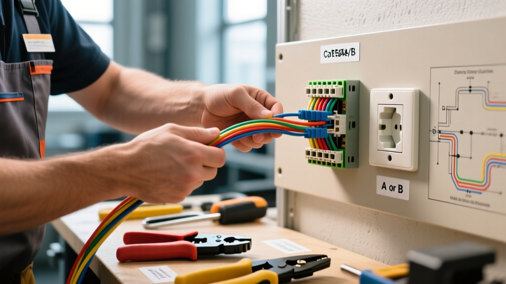
- O / B (Orange/Dark Blue): Reversing Valve solenoid.
The O vs. B Reversing Valve Dilemma
This is the most common edge case in heat pump wiring. The reversing valve changes the refrigerant flow direction. However, manufacturers disagree on when the valve should be energized:
- Energize on Cooling (O Terminal): Used by Carrier, Lennox, Trane, Goodman, and Mitsubishi. The valve defaults to heating mode when de-energized.
- Energize on Heating (B Terminal): Used almost exclusively by Rheem, Ruud, and some legacy Bryant models. The valve defaults to cooling mode when de-energized.
If you wire a Rheem system using the O terminal logic, the heat pump will blow cold air in the winter and hot air in the summer. Always check the manufacturer wiring diagram for heat pump reversing valve specifications before terminating the thermostat wire.
Communicating Systems vs. Conventional Wiring
As highlighted by EPA ENERGY STAR guidelines for ultra-efficient systems, variable-speed inverter heat pumps are now standard in many premium installations. These systems do not use the traditional R, Y, W, G, O/B analog wiring. Instead, they utilize a digital communication bus (often a 2-wire or 4-wire shielded cable) that sends serial data between the indoor module, outdoor inverter, and smart thermostat. When wiring a communicating system, polarity often matters, and using unshielded 18-gauge wire next to high-voltage lines will induce electromagnetic interference (EMI), causing the system to throw communication fault codes (e.g., Carrier Fault Code 13 or Trane Flash Code 4).
Step-by-Step Wiring Tutorial: Outdoor Unit Termination
- Secure the Conduit: Attach the LFMC to the outdoor unit knock-out using a liquid-tight connector. Ensure the grounding bushing is installed if using flexible metal conduit over 6 feet.
- Pull and Strip: Pull the THHN conductors through. Strip exactly 1/2 inch of insulation from the high-voltage wires. Stripping too much exposes live copper; stripping too little causes the lug to clamp onto the insulation, creating a high-resistance hot spot.
- Terminate High Voltage: Land L1 and L2 on the contactor lugs. Torque the lugs to the manufacturer specification (typically 35 to 45 in-lbs). Loose connections cause voltage drop and contactor pitting.
- Wire the Control Circuit: Connect the 24V Y and C wires to the contactor coil. Connect the O/B wire to the reversing valve solenoid spade connector.
- Grounding: Bond the equipment grounding conductor (EGC) to the factory-installed green grounding screw inside the control box. Never rely on the conduit alone for the primary ground path.
- Seal the Box: Apply a bead of silicone sealant around the conduit entry to prevent moisture and insects from entering the control compartment, which is a leading cause of defrost board corrosion.
Troubleshooting Matrix: Common Wiring Faults
When a system fails to operate, use this matrix to cross-reference symptoms with potential wiring errors based on the schematic.
| System Symptom | Likely Wiring Fault | Diagnostic Fix |
|---|---|---|
| Outdoor unit runs, but indoor blower does not. | Missing or broken G wire between thermostat and air handler. | Check continuity on the G wire. Verify 24V at the fan relay coil. |
| Heats in cooling mode, cools in heating mode. | Reversing valve wired to wrong terminal (O instead of B, or vice versa). | Move thermostat wire from O to B terminal. Check manufacturer schematic. |
| Contactor chatters or hums loudly. | Low voltage at contactor coil due to undersized 18-gauge wire over long runs. | Measure voltage at coil under load. If below 20V, upgrade to 16-gauge control wire. |
| Smart thermostat screen goes blank when heating calls. | Missing C wire; thermostat is stealing power through the Y or W circuit. | Run a dedicated C wire from the air handler transformer to the thermostat. |
| Breaker trips immediately upon startup. | L1 or L2 shorted to ground; compressor winding short. | Megger test the compressor windings to ground. Inspect control box for pinched wires. |
Final Thoughts on Code and Safety
Mastering the wiring diagram for heat pump systems requires a blend of old-school electrical fundamentals and modern digital diagnostics. Always verify the specific schematic taped inside the unit panel, as manufacturers frequently revise board layouts and terminal designations mid-production run. By adhering to strict torque specifications, respecting the O/B reversing valve logic, and staying current with NEC grounding and GFCI mandates, you ensure the system operates safely and efficiently for decades.