
Why Outboard Motors Demand a Dual Battery Architecture
Modern outboard motors, particularly high-horsepower four-strokes and direct-injection two-strokes, require massive Cold Cranking Amps (CCA) to turn over. Simultaneously, the modern angler or cruiser runs a suite of power-hungry electronics: multi-function displays, 36V trolling motors, live well pumps, and marine refrigeration. Relying on a single battery for both the engine starter and the house loads is a recipe for being stranded. Executing a proper 2 battery wiring diagram for boat applications ensures your cranking battery remains isolated and fully charged, guaranteeing your engine will start even if you have completely drained your house bank running sonar and coolers all day.
The Core Logic: Automatic Charging Relays (ACR)
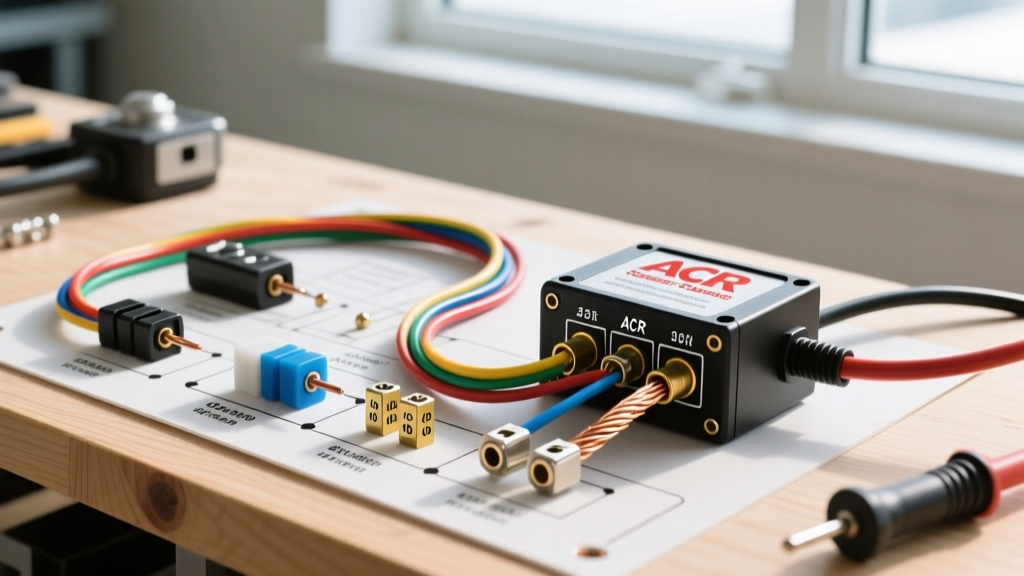
The most reliable and hands-free method for managing a dual-battery marine system is using an Automatic Charging Relay (ACR). Unlike manual 1-2-BOTH-OFF rotary switches, which rely on human memory and are prone to user error, an ACR automatically senses when the alternator is charging the starting battery. Once the starting battery reaches a specific voltage threshold (typically 13.0V for 30 seconds), the ACR closes an internal heavy-duty solenoid, paralleling the two batteries so the alternator can top off the house bank. When the engine stops and voltage drops below 12.35V for 10 seconds, the ACR isolates the banks, protecting the cranking battery from house loads.
ABYC E-11 Compliance Note: The American Boat & Yacht Council (ABYC) mandates that all ungrounded conductors connected directly to a battery must have overcurrent protection within 7 inches of the positive terminal. Always use Marine Battery Fuses (MRBF) or ANL fuses at the battery post, not just at the distribution panel. Refer to the ABYC Standards portal for the complete E-11 electrical code.
2026 Bill of Materials: Professional-Grade Components
Marine environments are unforgiving. Using automotive-grade parts will lead to galvanic corrosion and catastrophic failure within a single season. Here is the exact hardware required for a professional-grade installation:
- Automatic Charging Relay: Blue Sea Systems 7610 ACR (75/150 Amp). Retails around $115 in 2026. It handles the charging output of most standard outboard alternators (typically 35A to 50A).
- Terminal Fuses: Blue Sea Systems 5191 MRBF Terminal Fuse Block with 150A and 100A fuses. (~$45 per block). These mount directly to the battery post, satisfying the ABYC 7-inch rule.
- Marine Wire: Ancor Marine Grade Tinned Copper Wire. Do not use bare copper automotive wire. Tinned wire resists black oxide corrosion. Expect to pay roughly $4.50 to $6.00 per foot for 1/0 AWG in 2026.
- Terminals & Heat Shrink: Ancor adhesive-lined heat shrink terminals. The internal adhesive melts during heating, creating a waterproof seal that prevents capillary action from wicking moisture up the wire strands.
- Crimping Tool: A ratcheting hex-crimper (e.g., IWISS IWS-16 or Titan 11502, ~$60). Never use smash-crimpers or pliers for heavy-gauge marine battery cables; a gas-tight hex crimp is mandatory to prevent high-resistance hot spots.
Step-by-Step Motor Wiring Tutorial
Step 1: Mount the ACR and Bus Bars
Mount the Blue Sea 7610 ACR in a dry, well-ventilated area near the batteries but away from direct battery acid off-gassing. Install a heavy-duty negative bus bar nearby to serve as the common ground point for the ACR and the house battery negative terminal.
Step 2: Fuse the Positive Terminals
Install the MRBF fuse blocks directly onto the positive posts of both Battery 1 (Starting) and Battery 2 (House). For a standard 150A outboard alternator and starter draw, a 150A MRBF on the starting battery and a 100A MRBF on the house battery are typical baselines. Always size the fuse to protect the wire, not just the load.
Step 3: Run the Positive ACR Cables
Measure and cut 1/0 AWG tinned marine wire. Crimp 3/8-inch ring terminals on both ends using your hex crimper, and apply adhesive-lined heat shrink. Run one cable from the Battery 1 MRBF load side to the 'A' stud on the ACR. Run a second cable from the Battery 2 MRBF load side to the 'B' stud on the ACR. Torque the ACR nuts to 120 in-lbs.
Step 4: Ground the ACR
The ACR requires a ground reference to power its internal logic board and solenoid. Run a 10 AWG or 8 AWG wire from the ACR's negative stud to your common negative bus bar. Ensure the bus bar is tied to the negative posts of both batteries with heavy-gauge (1/0 AWG) equalization cables.
Step 5: Connect the Engine and House Loads
Connect your outboard motor's main positive harness directly to the Battery 1 positive bus or MRBF load stud. Connect your main DC distribution panel (which feeds the trolling motor, sonar, and bilge pumps) directly to the Battery 2 positive bus. This physical separation ensures the house loads can never pull voltage below the outboard's cranking threshold.
Wire Gauge and Fuse Sizing Matrix
Voltage drop is the silent killer of marine electronics. The ABYC recommends a maximum voltage drop of 3% for critical loads (navigation lights, engine controls) and 10% for non-critical loads. The chart below outlines the minimum wire gauge required based on the maximum alternator output and the one-way cable distance from the alternator/battery to the ACR.
| Max Current (Amps) | One-Way Distance (ft) | Minimum Wire Gauge (AWG) | Recommended MRBF Fuse |
|---|---|---|---|
| 50A | 0 - 5 ft | 4 AWG | 60A |
| 50A | 6 - 10 ft | 2 AWG | 70A |
| 100A | 0 - 5 ft | 1/0 AWG | 125A |
| 100A | 6 - 15 ft | 2/0 AWG | 150A |
| 150A+ | 0 - 10 ft | 2/0 AWG | 200A |
The 2026 Lithium Edge Case: LiFePO4 House Banks
As of 2026, lithium iron phosphate (LiFePO4) batteries have become the standard for marine house banks due to their weight savings and 100% usable depth of discharge. However, you cannot use a standard ACR with a lithium house bank. The BMS (Battery Management System) inside a lithium battery will disconnect the cells if charging voltage exceeds 14.6V, which can cause voltage spikes that destroy your outboard's alternator diodes.
If Battery 2 is lithium, you must alter the 2 battery wiring diagram for boat setups by replacing the ACR with a DC-to-DC battery charger, such as the Victron Energy Orion XS. The Orion XS isolates the banks completely and steps down the alternator's voltage to a safe, programmable lithium charging profile, protecting both your alternator and your expensive lithium cells.
Troubleshooting Common Failure Modes
Rapid ACR Clicking (Hysteresis Failure)
If you hear the ACR rapidly clicking on and off while the engine is idling, your house battery is likely heavily depleted and pulling the combined system voltage below the ACR's disconnect threshold (12.35V). The alternator cannot keep up with the massive absorption current demanded by the dead house bank. Solution: Install an Alternator Field Disconnect (AFD) or use an ACR with an under-voltage lockout feature to prioritize the starting battery until it reaches full absorption.
Outboard Alternator Whine in Audio Systems
Paralleling batteries can introduce alternator whine into marine amplifiers. This is usually caused by poor grounding or using the engine block as a ground return for stereo equipment. Solution: Run a dedicated, heavy-gauge ground wire from the amplifier's negative terminal directly to the house battery's negative bus bar, bypassing the engine block entirely.
Corroded Terminals and High Resistance
If your ACR fails to combine, check for voltage drop across your crimps. A poorly executed crimp using non-adhesive heat shrink will allow salt air to penetrate, creating copper oxide. Copper oxide is a semiconductor; it resists current flow and generates immense heat. Always perform a thermal scan with an infrared thermometer after your first hour of operation. Any terminal exceeding 120°F (49°C) must be cut off and re-crimped.
For further reading on marine electrical safety and automatic charging relay schematics, consult the Blue Sea Systems ACR documentation library, which provides detailed PDF wiring matrices for complex multi-bank configurations.