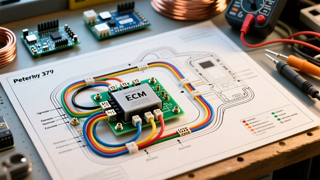

Introduction to the Peterbilt 379 Electrical Architecture
The Peterbilt 379, manufactured from 1987 to 2007, remains one of the most iconic and heavily restored heavy-duty trucks on North American roads. Whether you are performing a full frame-off restoration, troubleshooting a parasitic draw, or integrating a modern Auxiliary Power Unit (APU), understanding the wiring diagram for Peterbilt 379 models is non-negotiable. Unlike modern multiplexed systems found in the 579 or 589, the 379 relies on a robust, hardwired relay-and-fuse architecture utilizing SXL (cross-linked polyethylene) insulated copper wiring rated for continuous 125°C operation.
In 2026, with OEM replacement harnesses costing between $2,800 and $4,500 depending on the wheelbase and sleeper configuration, owner-operators and fleet technicians must be adept at reading schematics, performing voltage-drop tests, and splicing circuits without compromising the chassis integrity. This guide breaks down the core domains of the 379 electrical system, ECM datalink pinouts, and critical failure modes.
The Three Primary Harness Domains
When reviewing a factory Peterbilt 379 schematic, the electrical system is divided into three distinct physical harnesses. Understanding where one ends and the other begins is the first step in effective troubleshooting.
1. The Chassis Harness
The chassis harness is the backbone of the truck. It routes from the battery boxes (typically located on the left saddle tank or behind the cab) forward to the headlights, and rearward to the DOT lighting, ABS modules, and trailer receptacles. It is wrapped in split-loom corrugated tubing and secured with UV-resistant zip ties and P-clips every 18 inches. The wiring diagram for the chassis harness will show heavy-gauge cables (1/0 AWG to 4 AWG) for the starter and alternator, stepping down to 10 AWG and 12 AWG for lighting circuits.
2. The Cab Harness
This harness powers the dash gauges, HVAC blower motors, marker switches, and the sleeper environment controls. It connects to the chassis harness via the bulkhead connector—a critical 70-pin or 90-pin (depending on the model year and sleeper spec) pass-through located on the firewall behind the driver’s side kick panel.
3. The Sleeper Harness (Optional)
For Unibilt or stand-up sleeper configurations, a dedicated harness routes 12V DC power and 120V AC shore power. In later model years (2004-2007), this included integration points for RigMaster or Carrier ComfortPro APUs, requiring specific 4-pin control signal splices detailed in the sleeper addendum of the wiring diagram.
Engine ECM and J1939 Datalink Pinouts
The Peterbilt 379 was predominantly spec'd with Caterpillar (C15, 3406E) or Cummins (ISX, N14) engines. Communication between the engine Electronic Control Module (ECM), the transmission TCM, and the dash gauges occurs over the SAE J1939 Controller Area Network (CAN) bus. According to the SAE J1939 standard, this high-speed datalink operates at 250 kbps.
Pro-Tip for Diagnostics: If your dash gauges are sweeping erratically or the check engine light is flashing a CID 231 (Loss of Communication), do not immediately replace the ECM. Check the J1939 terminating resistors first. You should measure exactly 60 ohms across the CAN-H and CAN-L pins with the batteries disconnected. If you read 120 ohms, one of the two terminating resistors (usually located inside the ECM and the dash cluster) has failed or the circuit is open.
Standard OEM 9-Pin Diagnostic Connector Pinout
- Pin A: Battery Positive (Unswitched 12V)
- Pin B: Battery Ground
- Pin C: J1939 CAN High (Yellow wire, 2.5V - 3.5V)
- Pin D: J1939 CAN Low (Green wire, 1.5V - 2.5V)
- Pin E: J1708 Data Link (+)
- Pin F: J1708 Data Link (-)
- Pins G, H, J: OEM proprietary / Auxiliary
Critical Failure Modes and Voltage Drop Testing
Because the 379 is a legacy platform, electrical gremlins are almost always tied to corrosion, chafing, or poor grounding. When using the wiring diagram to trace a fault, skip the continuity test and perform a voltage drop test under load. A healthy circuit should exhibit less than 0.1V drop across any single connection or switch.
The Bulkhead Connector Corrosion Issue
The cab-to-chassis bulkhead connector is notorious for moisture ingress. Water wicks into the pins via capillary action, causing copper oxidation (green crust) that increases resistance. This manifests as dim dash lights, slow HVAC blower speeds, or erratic wiper operation. The Fix: Disconnect the bulkhead, clean the pins with electrical contact cleaner, and pack the connector cavity with a dielectric grease like Nyogel 760G. If pins are severely pitted, replacement backshells and Deutsch-style crimp pins are required.
Left Frame Rail Ground Studs
Peterbilt routes the majority of the chassis lighting and rear ABS grounds to a cluster of 3/8-inch and 1/2-inch copper ground studs welded to the left frame rail, just ahead of the rear axles. Road spray and winter de-icing chemicals corrode these star washers and lugs. Always disconnect, wire-brush the frame rail to bare metal, apply a zinc-rich anti-seize compound, and torque to 35 lb-ft.
Wire Color Standards and Gauge Reference Matrix
While custom orders can alter wire colors, standard Peterbilt 379 wiring diagrams generally adhere to the following color-coding and gauge sizing for primary circuits. Adhering to NFPA 70 (National Electrical Code) guidelines for DC ampacity in mobile applications is critical when replacing damaged sections of wire.
| Circuit Function | Standard Wire Color | Recommended Gauge (AWG) | Max Fuse / Breaker Size |
|---|---|---|---|
| Headlights (Low/High) | Red / White Tracer | 10 AWG | 20A |
| Clearance / Marker Lights | Brown | 14 AWG | 10A |
| Turn Signals / Hazards | Yellow (Left) / Green (Right) | 12 AWG | 15A |
| Stop / Tail Lights | Red | 12 AWG | 15A |
| ECM Ignition (Switched) | White | 10 AWG | 20A |
| Starter Solenoid Trigger | Purple / Yellow | 12 AWG | 15A |
Upgrading to LED and Auxiliary Lighting
Many owner-operators updating their 379 in 2026 are swapping out incandescent bulbs for LED arrays. While LEDs draw significantly less current, they introduce a specific wiring challenge: hyper-flashing and bulb-out warnings. The 379's flasher modules are often thermal or load-dependent. Furthermore, the DOT lighting regulations outlined in 49 CFR Part 393 require specific candela outputs and visibility angles that cheap LED replacements often fail to meet.
- Install Electronic Flashers: Replace the factory thermal flasher relay under the dash with a heavy-duty, solid-state electronic flasher rated for LED loads (e.g., a Novita EP35 or equivalent). This prevents hyper-flashing without needing to splice in dummy load resistors, which generate excessive heat.
- Auxiliary Light Relays: If adding roof-mounted amber strobes or LED light bars, never wire them directly through the factory cab toggle switches. The 379 dash switches are typically rated for only 10A to 15A. Use the switch to trigger a 30A Bosch-style relay mounted in the engine bay, pulling heavy-gauge power directly from the battery junction block.
- Seal All Splices: Use marine-grade heat shrink with adhesive-lined interiors (dual-wall) for any outdoor splices. Standard vinyl electrical tape will degrade and unpeel within six months due to engine bay heat and UV exposure.
Summary
Navigating the wiring diagram for Peterbilt 379 trucks requires an understanding of its distinct chassis, cab, and sleeper domains, as well as the SAE J1939 datalink that governs its powertrain. By focusing on voltage-drop diagnostics, maintaining the bulkhead and ground studs, and respecting wire gauge standards during modern LED upgrades, you can ensure this legendary platform remains electrically reliable for years to come.