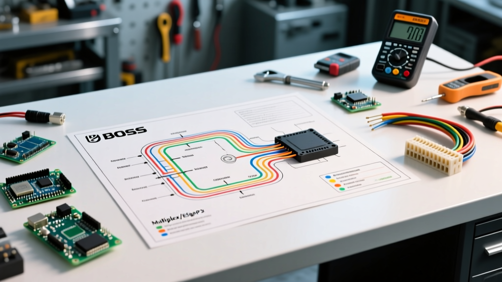

Mastering the Schematic: A Deep Dive into Boss Snow Plow Electronics
When a hydraulic plow fails in the middle of a commercial snow route, guessing which wire to bypass or which solenoid to swap is a fast track to frying a $600 Motor Solenoid Controller (MSC). Modern Boss snow plows—ranging from the heavy-duty V-DXT to the versatile RT3 Straight Blade—rely on sophisticated multiplex electrical systems rather than the simple relay-click circuits of the past. To effectively diagnose these systems, a mechanic or fleet owner must know how to properly interpret a wiring diagram for Boss snow plow configurations.
This guide moves beyond basic continuity checks. We will break down the multiplex architecture, map specific schematic symbols to real-world failure modes, and provide a step-by-step diagnostic matrix using a Digital Multimeter (DMM). Whether you are dealing with a dead Smart Hitch 2 system or a localized wing failure on a V-plow, the schematic is your most critical troubleshooting tool.
The Evolution of Boss Electronics: Relay vs. Multiplex
Before diving into the diagram, it is vital to understand the generational shift in Boss plow electronics. Older Boss systems utilized a traditional relay-based setup where the in-cab controller sent direct 12V signals to heavy-duty starter-style solenoids. If a plow didn't move, you listened for the relay click.
Today's Boss systems utilize a Multiplex architecture. In this setup, the in-cab controller sends a low-amperage data signal to the MSC (the 'brain' mounted on the plow). The MSC then interprets this signal and triggers the appropriate hydraulic solenoid valve.
Expert Insight: Because the multiplex system relies on data communication rather than raw 12V power delivery to the cab switch, using a standard 12V test light on the control wires will yield false readings and can potentially short the MSC data bus. A high-impedance Digital Multimeter (DMM) is mandatory for modern Boss diagnostics.
Decoding the Schematic: Essential Wire Colors and Symbols
A standard Boss wiring diagram will separate the high-current power circuit from the low-current control circuit. Below is a reference table for the most common wire color codes and schematic symbols found in Boss RT3 and Multiplex systems (always verify against your specific model year's schematic, as tracer colors can vary).
| Circuit Type | Wire Color (Typical) | Schematic Symbol / Function | Diagnostic Target |
|---|---|---|---|
| Main Power | Heavy Red | Battery (+) to MSC / Motor | Check for 12.6V at MSC input; inspect 30A+ main fuse. |
| Main Ground | Heavy Black | Motor / MSC to Chassis (-) | Perform voltage drop test; clean chassis grounding point. |
| Lift Solenoid Trigger | Orange (or Orange tracer) | MSC Output to Lift Coil | Check for 12V output at MSC when 'Up' is pressed. |
| Lower Solenoid Trigger | Brown (or Brown tracer) | MSC Output to Lower Coil | Verify coil resistance (typically 2-6 ohms). |
| Left Angle Trigger | Green (or Green tracer) | MSC Output to Left Angle Coil | Check for open circuit if wing fails to extend. |
| Right Angle Trigger | Yellow (or Yellow tracer) | MSC Output to Right Angle Coil | Inspect connector pins for corrosion/push-out. |
| Data / Comm | Red/White or Green/White | Cab Controller to MSC | Check for pulsing DC voltage or specific resistance. |
Step-by-Step 13-Pin Vehicle Harness Diagnostics
The 13-pin connector is the umbilical cord between the truck and the plow. It carries main power, ground, ignition sense, and multiplex data lines. When a plow exhibits 'dead' symptoms (no lights, no movement), the 13-pin harness is the first place the wiring diagram directs you.
1. The Voltage Drop Test on Main Power
According to Fluke's automotive testing guidelines, a voltage drop test is the only reliable way to find high resistance in a high-amperage circuit. A standard continuity test will show a good connection even if only one strand of wire is intact, which will instantly fail under the 150+ amp draw of a plow motor.
- Set your DMM to DC Volts.
- Connect the red probe to the truck's battery positive terminal and the black probe to the heavy Red wire pin on the plow side of the 13-pin connector.
- Activate the plow motor (or turn on the plow lights to create a load).
- A reading above 0.2V indicates excessive resistance in the power cable, usually due to internal corrosion or a failing crimp terminal.
2. Verifying the Ignition and Ground Pins
The MSC requires an ignition sense signal to 'wake up.' If the diagram shows Pin 3 (or your specific model's ignition pin) is dead, the MSC will remain in sleep mode to prevent battery drain. Use your DMM to verify 12V+ at the ignition pin with the truck running. Simultaneously, test the ground pins. A poor ground on the 13-pin connector will cause the multiplex data lines to float, resulting in erratic solenoid firing or complete system lockout.
Troubleshooting Matrix: Mapping Symptoms to the Diagram
Use this matrix to cross-reference your physical symptoms with the logical flow of the Boss wiring diagram. This assumes the main power and 13-pin connections have already been verified.
| Physical Symptom | Schematic Circuit to Trace | Probable Failure Mode | Corrective Action / Test |
|---|---|---|---|
| Plow drops slowly when raised | Lower Valve Circuit (Brown) | Lower solenoid coil shorting internally or MSC leaking voltage. | Disconnect lower coil. If plow holds, replace coil ($40-$70). If it still drops, check MSC output for parasitic voltage. |
| Left wing angles, Right wing dead | Right Angle Trigger (Yellow) | Open circuit in trigger wire or failed coil. | Measure resistance across Right coil pins. If OL (Open Loop), replace coil. If ~4 ohms, check wire continuity from MSC. |
| Motor clicks but won't turn | Motor Solenoid Control Circuit | High resistance on motor ground or failed motor brushes. | Bypass motor solenoid with a heavy jumper. If motor spins, test solenoid coil and MSC trigger. If motor doesn't spin, rebuild/replace motor. |
| Plow lights flicker or fail | Lighting Module / Iso-Module | Headlamp adapter harness mismatch or bad ground. | Verify correct HB4/HB5 adapter harness. Check lighting module ground strap to truck chassis. |
| Entire system dead, no cab display | Main Power / Data Comm | Blown main fuse, severed data wire, or dead MSC. | Check 30A+ fuse near battery. Check data wire continuity. If power and ground are good at MSC but no data out, replace MSC ($450-$650). |
Real-World Edge Cases the Diagram Won't Show You
Wiring diagrams represent ideal conditions. In the field, environmental factors create edge cases that require mechanical intuition combined with electrical knowledge.
The Steering Box Chafe Point
On many heavy-duty trucks (e.g., Ford F-250/F-350, Ram 2500/3500), the main power cable and the 13-pin harness are routed near the steering box or the front suspension components. Over a season of vibration and salt exposure, the harness loom can wear through, causing the multiplex data wires to short against the chassis. The diagram won't show a 'short to ground at the steering box,' but if your data line shows 0.0V and 0 ohms to ground, physically trace the harness through the engine bay pinch points.
MSC Connector Corrosion and 'Pin Push-Out'
The MSC module is typically mounted on the driver's side of the plow A-frame, directly in the blast zone of road salt. Even with dielectric grease, the multi-pin connectors can suffer from galvanic corrosion. Furthermore, when technicians unplug the harness in freezing weather, the stiffened wires can cause 'pin push-out'—where the metal terminal pushes backward out of the plastic connector housing. Always use a pin extraction tool to verify terminal retention when a specific solenoid circuit shows an open circuit on the diagram, despite the wire testing good.
Safety Protocols and Essential Tooling
Working on 12V DC systems with high amperage potential poses severe arc-flash and burn risks. As noted in OSHA's electrical safety guidelines, even low-voltage systems can cause catastrophic thermal burns if a short circuit occurs across a high-capacity battery.
- Disconnect the Main Power: Always pull the main plow fuse or disconnect the heavy Red cable at the battery before performing resistance checks or swapping solenoids.
- Use a Load Tester: A DMM is great for diagnostics, but a dedicated carbon pile load tester is required to verify the truck's battery and alternator can handle the 150A+ spike of a plow motor under load.
- Dielectric Grease: Never use standard chassis grease on electrical pins. Use a high-quality, non-conductive dielectric grease (like NYE 812 or equivalent) on all 13-pin and MSC connectors to prevent moisture ingress.
For official schematic downloads, technical service bulletins (TSBs), and warranty information, always refer to the Boss Snowplows official support portal or consult an authorized Boss dealer. Having the exact, year-specific wiring diagram for your Boss snow plow model in hand before you pick up a multimeter is the single most important step in achieving a fast, accurate, and cost-effective repair.