
Understanding the Atwood 12V DC Architecture
Atwood RV furnaces—now largely integrated into Dometic and Airxcel product lines, encompassing the classic AFM, AFS, DFS series, and legacy Hydro Flame models—rely on a straightforward but highly sensitive 12V DC electrical system. Unlike residential HVAC systems that utilize 24V AC control circuits powered by a step-down transformer, RV furnaces operate entirely on the vehicle's 12V DC house battery bank. Because the control board, blower motor, gas valve, and igniter all draw from this single low-voltage source, voltage drop is the primary enemy of a reliable heating cycle.
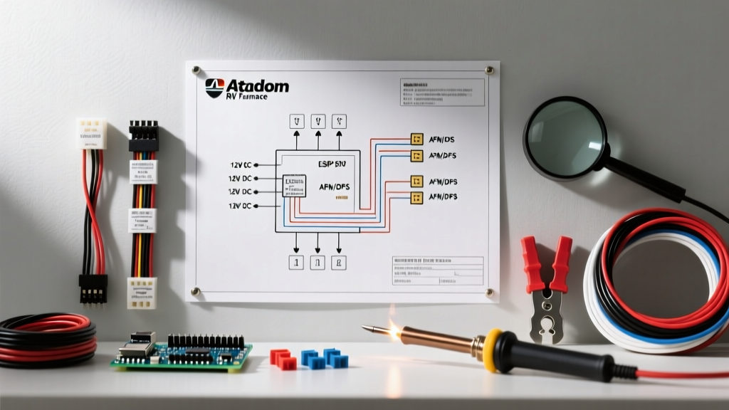
When analyzing a wiring diagram for Atwood RV furnace assemblies, it is critical to understand that the control board does not merely switch power; it actively monitors voltage thresholds. If the voltage at the board's main terminals drops below 10.5V DC during the blower's startup surge (which can pull 7.5 to 9 amps on models like the AFM25 or DFS35), the microprocessor will trigger an immediate safety lockout. Therefore, proper wire gauge selection and pristine grounding are just as important as the physical pinout connections.
Core Wiring Diagram: AFM, AFS, and DFS Pinout Matrix
The standard Atwood/Dometic control board (often replaced with part numbers like the Dometic 3106995.000 or equivalent aftermarket boards) utilizes a multi-pin connector for the primary harness. Below is the definitive pinout reference for the standard 6-pin and auxiliary connectors found on most post-2010 Atwood forced-air furnaces.
| Wire Color | Function | Destination | Voltage / State |
|---|---|---|---|
| Red (Heavy) | 12V+ Main Power | Control Board Pin 1 / Battery Pos | 12.0V - 13.8V DC (Constant) |
| White (Heavy) | 12V- Ground | Control Board Pin 2 / Chassis | 0V (Must have <0.2Ω to battery) |
| Blue or Yellow | Thermostat Call | Control Board Pin 3 / T-Stat | 12V when calling for heat |
| Black | Blower Motor (+) | Blower Assembly | 12V during purge & run cycles |
| Orange | Sail Switch Loop | Control Board Pin 4 / Airflow | Closes circuit when airflow > 250 CFM |
| Brown | Limit Switch Loop | Control Board Pin 5 / Heat Exchanger | Normally Closed (Opens at 190°F) |
Thermostat Integration and Control Circuit Wiring
The thermostat circuit on an Atwood furnace is remarkably simple. It functions as a basic Single-Pole Single-Throw (SPST) switch. When the ambient temperature drops below the set point, the thermostat's internal bimetallic strip or digital relay closes the circuit, sending 12V+ from the Red wire through the Blue/Yellow thermostat wire back to Pin 3 on the control board.
Expert Note on Digital Upgrades: If you are upgrading from an analog dial to a digital RV thermostat (such as the Dometic Single Zone LCD or the Micro-Air EasyTouch), ensure the new unit is specifically rated for 12V DC millivolt/direct-wire systems. Standard residential smart thermostats (like Nest or Ecobee) require 24V AC and a C-wire, and will instantly destroy the Atwood control board's logic gate if wired directly to the 12V DC harness.
Critical Failure Modes: Voltage Drop and Grounding
Before assuming a control board is faulty, 90% of Atwood furnace wiring issues can be traced back to two specific electrical phenomena: voltage drop on the positive leg, and inductive kickback on the ground leg.
The 10.5V Lockout Threshold and Wire Gauge
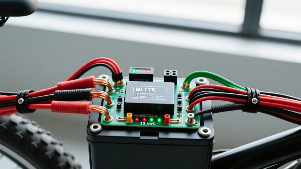
The blower motor on an Atwood AFM25 draws roughly 8 amps during the initial 15-second purge cycle. If your RV manufacturer used 14 AWG wire for a 25-foot run from the DC distribution panel to the furnace, the resistance of the wire will cause a voltage drop. According to Ohm's law, a 25-foot run of 14 AWG copper carrying 8 amps will drop nearly 0.8 volts. If your battery is resting at 11.8V, the voltage arriving at the furnace control board will be 11.0V. Once the motor engages, the localized voltage at the board's microprocessor can sag below the critical 10.5V threshold, causing the board to reset mid-cycle and flash a diagnostic error code.
The Fix: Always use 12 AWG stranded copper wire for any furnace power run exceeding 10 feet. At roughly $0.45 per foot, this minor material upgrade prevents the majority of unexplained furnace lockouts.
Inductive Kickback and Gas Valve Grounding
The Atwood gas valve is a direct-acting 12V DC solenoid. When the control board cuts power to the gas valve at the end of the heating cycle, the collapsing magnetic field inside the solenoid coil generates a reverse voltage spike (inductive kickback). If the gas valve shares a ground wire or a ground bus bar with the blower motor, this spike can travel back into the control board, eventually frying the MOSFETs that regulate the igniter. Always ensure the gas valve has a dedicated, clean ground path directly to the chassis or battery negative.
Step-by-Step Diagnostic Wiring Verification
When troubleshooting an Atwood furnace that fails to ignite, follow this exact sequence with a digital multimeter set to DC Volts:
- Measure Static Voltage: Probe the Red (12V+) and White (Ground) wires directly at the control board pins with the furnace off. You should read between 12.2V and 13.6V.
- Measure Voltage Under Load: Turn the thermostat up to call for heat. As soon as the blower motor engages, keep your probes on the board pins. If the voltage drops below 11.0V, you have a wiring gauge issue or a failing battery, not a bad board.
- Verify the Sail Switch: If the blower runs but the igniter never clicks, probe the Orange wire at the board. It should show 12V when the sail switch is closed by the blower's airflow. If it reads 0V, the sail switch is stuck open, or the blower is spinning too slowly due to a bad motor ground.
- Check the Igniter/Sense Rod Wire: This single high-voltage wire carries both the spark pulse and the microamp flame sense signal. Ensure the spade connector is completely free of corrosion. Even a microscopic layer of oxidation will block the microamp return signal, causing a false 'no flame' lockout.
Interpreting Control Board LED Blink Codes
Modern Atwood/Dometic control boards feature a diagnostic LED visible through the exterior exhaust/vent cover. Count the flashes to identify the specific wiring or component fault:
- 3 Blinks (Limit Switch / Airflow Fault): The limit switch opened during operation. This is rarely a bad switch; it is almost always caused by low voltage to the blower motor, resulting in insufficient CFM to push heat through the exchanger, or a blocked exterior vent.
- 4 Blinks (Ignition Lockout): The board sent the spark, opened the gas valve, but did not detect the microamp flame rectification signal. Check the igniter wire routing (it must not touch the metal chassis) and clean the sense rod with steel wool.
- 5 Blinks (Gas Valve Relay Fault): Internal board failure. The board is detecting voltage on the gas valve circuit when it should be open. Requires a control board replacement ($95 - $145 for OEM parts).
RVIA Compliance and Safety Standards
When modifying or repairing RV furnace wiring, all work must adhere to the standards set forth by the Recreational Vehicle Industry Association (RVIA) and the low-voltage grounding principles outlined in NFPA 70 (National Electrical Code). Specifically, all 12V DC connections inside the furnace compartment must be made using heat-shrink butt connectors or closed-end crimp caps. Wire nuts are strictly prohibited in RV mobile applications due to constant vibration, which can loosen the connection and create a high-resistance arc fault. For official schematics and warranty support regarding integrated Atwood systems, technicians should consult the Dometic Support Portal.
Frequently Asked Questions
Can I wire my Atwood furnace directly to a solar charge controller?
No. The furnace blower motor generates significant electrical noise and voltage spikes. Wiring it directly to a solar controller's load terminals can damage the controller's internal relays. Always wire the furnace to a dedicated 15-amp fused circuit on the RV's main 12V DC distribution busbar.
Why does my furnace work on shore power but not on battery?
When plugged into shore power, your RV's power converter supplies a steady 13.6V DC to the busbar, overcoming minor voltage drops in undersized wiring. When running purely on battery (resting at 12.0V), that same voltage drop pushes the board below the 10.5V threshold. Upgrade your positive and negative feed wires to 12 AWG to resolve this.