
Understanding the Modern Wiring Diagram for Pot Lights
Installing recessed lighting, commonly known as pot lights or can lights, has evolved significantly over the last decade. While older incandescent housings required strict thermal clearances and high-wattage circuits, the 2026 standard relies on ultra-efficient, integrated LED housings and wafer-style downlights. However, the fundamental electrical principles and National Electrical Code (NEC) requirements for routing, terminating, and protecting these circuits remain rigorous. This step-by-step walkthrough breaks down the exact wiring diagram for pot lights, focusing on a standard 15-amp residential lighting circuit using 14/2 NM-B (Romex) cable and modern IC-rated (Insulation Contact) LED housings.
Materials, Tools, and 2026 Cost Breakdown
Before pulling any wire, you must gather code-compliant materials. Using the wrong wire gauge or non-IC-rated housings in insulated ceilings is a leading cause of thermal cutoff trips and residential electrical fires. Below is a precise bill of materials for a standard 6-light daisy-chain installation.
| Material / Tool | Specific Model / Type | Estimated Cost (2026) | Purpose & Code Note |
|---|---|---|---|
| LED Recessed Housing | Halo H750T 6-inch IC-Rated | $28.00 - $34.00 / ea | IC-rated allows direct insulation contact; Air-Tite prevents drafts. |
| Branch Circuit Wire | Southwire 14/2 NM-B (250ft roll) | $98.00 - $115.00 | 14 AWG copper for 15A circuits. Use 12/2 NM-B if on a 20A breaker. |
| Wire Connectors | Wago 221 Lever Nuts (50-pack) | $14.50 | UL-listed push-in lever connectors; vastly superior to twist-on wire nuts. |
| Voltage Tester | Klein Tools NCVT-3 Dual Range | $35.00 | Detects 12V to 1000V AC. Mandatory for verifying dead circuits. |
| Cable Staples | Gardner Bender 1/2-inch NM Staples | $6.00 / box | Required by NEC 334.30 for securing NM-B cable to framing. |
Step 1: Circuit Verification and Safety Lockout
Never assume a circuit is dead based on the wall switch position. Pot lights are often wired into shared circuits with receptacles or other lighting zones. Navigate to your main service panel and turn off the corresponding 15A or 20A single-pole breaker. Apply a lockout/tagout (LOTO) device to the breaker panel to prevent accidental re-energization while you are working in the ceiling cavity. Use the Klein Tools NCVT-3 to test the existing junction box or switch loop. Test the NCVT-3 on a known live circuit first to verify the tool's battery and sensor are functioning correctly, then test the target pot light circuit. Only proceed when the tester remains completely silent and unlit.
Step 2: Rough-In and Cable Routing (NEC 334.30)
The physical routing of your 14/2 NM-B cable dictates the longevity and safety of your installation. According to NFPA 70 (National Electrical Code) Article 334.30, nonmetallic-sheathed cable must be supported and secured by staples, cable ties, straps, hangers, or similar fittings designed and installed so as not to damage the cable.
- First Staple: The cable must be secured within 12 inches of the junction box (either the switch box or the first pot light housing).
- Subsequent Staples: The cable must be secured at intervals not exceeding 4.5 feet (1.4 meters).
- Bored Holes: When running wire through ceiling joists, drill holes in the center of the joist (at least 1.25 inches from the edge) to prevent nail-plate punctures from drywall screws.
Step 3: The Core Wiring Diagram for Pot Lights
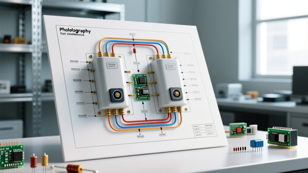
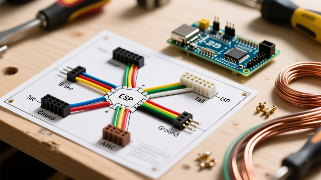
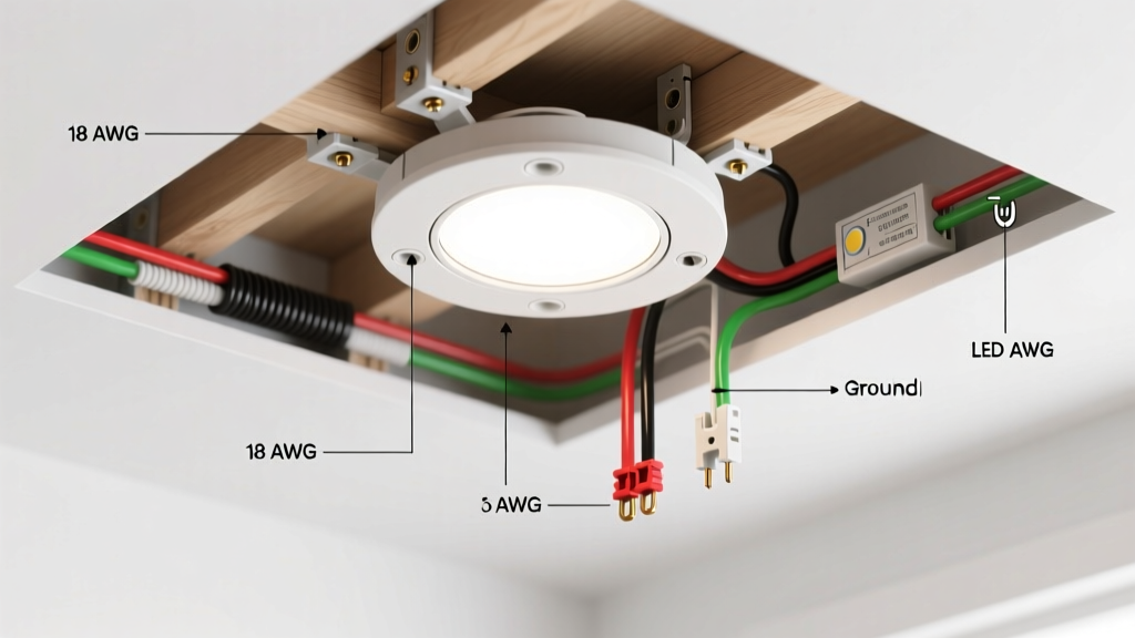
The most common topology for residential pot lights is the daisy-chain (loop-in/loop-out) configuration. In this setup, power enters the first light's junction box, and a secondary cable runs from the first light to the second, continuing down the line. Modern LED housings like the Halo H750T feature built-in, code-compliant junction boxes with push-in or screw-terminal quick connectors, eliminating the need for separate octagon boxes above the ceiling.
Anatomy of the Daisy-Chain Connection
At each pot light junction box, you will be marrying three sets of wires: the Line (power coming from the switch or previous light), the Load (power continuing to the next light), and the Pigtail (the short wire harness attached to the LED module).
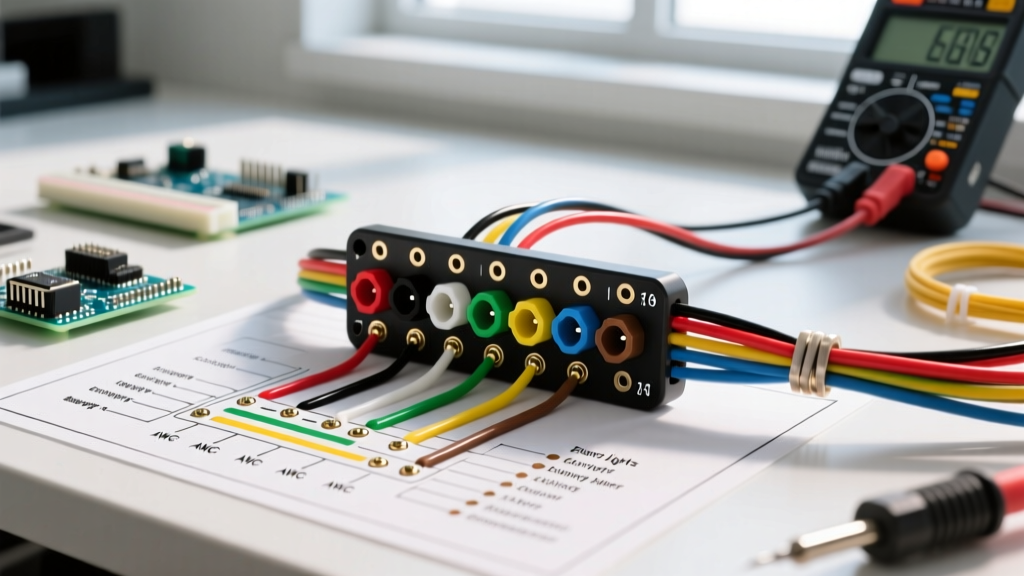
- Ground (Bare/Green): Connect the bare copper from the Line cable, the bare copper from the Load cable, and the green ground pigtail from the LED module. In a Wago 221 3-port lever nut, these three wires share a single connection block.
- Neutral (White): Connect the white neutral from the Line, the white neutral from the Load, and the white neutral pigtail from the LED module. This completes the return path for the 120V AC circuit.
- Hot (Black): Connect the black hot from the Line, the black hot from the Load, and the black hot pigtail from the LED module. This carries the switched 120V AC current to the LED driver.
Step 4: Box Fill Calculations and IC-Rating Compliance
Even though modern LED housings have integrated junction boxes, you must still respect NEC Article 314.16 regarding box fill capacity. Overcrowding a junction box causes wire insulation damage and excessive heat buildup. For 14 AWG wire, the NEC assigns a volume allowance of 2.0 cubic inches per conductor. A standard integrated LED junction box typically offers 12 to 15 cubic inches of space, which comfortably accommodates the Line, Load, and Pigtail conductors (totaling 6 current-carrying and ground conductors, requiring 12 cubic inches). Always verify the stamped cubic-inch rating on the housing before terminating.
Furthermore, if your ceiling cavity is insulated (common in attics or top-floor rooms), you must use IC-rated (Insulation Contact) housings. Non-IC housings require a strict 3-inch clearance from all thermal insulation. If insulation touches a non-IC housing, the internal thermal protection switch will trip, causing the light to shut off randomly as it heats up. ENERGY STAR certified recessed downlights almost universally mandate IC-rating and Air-Tite (AT) sealing to prevent conditioned indoor air from escaping into the attic.
Step 5: Termination Best Practices with Lever Nuts
While traditional twist-on wire nuts have been the industry standard for decades, Wago 221 lever connectors are the 2026 professional standard for pot light wiring. They eliminate the risk of 'cold joints' (where a wire nut is twisted but fails to grip the solid copper core) and allow for easy modifications.
Pro-Tip for Stripping NM-B: Strip exactly 11mm (7/16 inch) of insulation from the 14 AWG solid copper conductors. The Wago 221 features a built-in stripping gauge on the side of the housing. Insert the wire, push the orange lever up, and pull the wire to verify a secure mechanical lock. Tug gently on each wire to ensure it is fully seated.
Troubleshooting: Dimmer Compatibility and Flickering
The most frequent post-installation failure mode for LED pot lights is flickering or 'strobing' when paired with an incompatible dimmer switch. Older incandescent dimmers use leading-edge (TRIAC) technology, which chops the AC sine wave aggressively. LED drivers, however, require trailing-edge (ELV) or specifically tuned LED+ dimmers to operate smoothly at low voltages.
If your newly wired pot lights flicker below 30% brightness, or if they 'pop' on when the switch is engaged, replace the wall switch with a Lutron Diva DVCL-153P or a Leviton Decora DSL06. These dimmers feature adjustable low-end trim dials, allowing you to set the minimum voltage threshold just above the LED driver's dropout point, completely eliminating flicker and extending the lifespan of the integrated LED diodes.
Summary of the Wiring Sequence
By adhering to NEC staple spacing, respecting box fill limits, utilizing IC-rated housings, and terminating with lever-nut connectors, your recessed lighting installation will be safe, code-compliant, and maintenance-free for the 50,000-hour rated lifespan of the LED modules. Always pull municipal permits for new circuit runs and schedule a rough-in inspection before closing the ceiling with drywall.