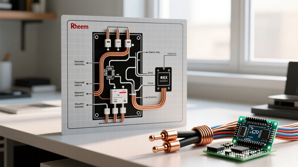

The Reality of Electric Tankless: Planning Before You Wire
Transitioning to an electric tankless water heater is one of the most demanding electrical upgrades a residential property can undergo. Unlike gas models that require venting, or traditional 4500-watt storage tanks that run on a single 30-amp breaker, high-capacity electric tankless units draw massive instantaneous current. If you are searching for a Rheem tankless electric water heater wiring diagram, you are likely looking at the Rheem RTEX series. These units range from 13kW to 36kW, meaning your electrical panel must be prepared to deliver anywhere from 54 to 150 amps of continuous 240V power on demand.
According to the U.S. Department of Energy, while tankless heaters eliminate standby heat loss, their peak electrical demand requires rigorous infrastructure planning. This installation planning guide breaks down the exact wiring diagrams, breaker configurations, wire gauges, and torque specifications required for a safe, code-compliant Rheem RTEX installation in 2026.
Rheem RTEX Series: Electrical Requirements Matrix
The Rheem RTEX line modulates heating elements based on flow rate. However, the wiring diagram must support the maximum amperage draw. Below is the definitive specification chart for the most common residential models. Pricing reflects average 2026 retail market rates.
| Model | Max kW (240V) | Max Amps | Breaker Requirement (Double Pole) | Min. Wire Gauge (Copper) | Avg. Cost (2026) |
|---|---|---|---|---|---|
| RTEX-13 | 13 kW | 54 A | 1 x 60A | 6 AWG | $290 - $320 |
| RTEX-18 | 18 kW | 75 A | 2 x 40A | 8 AWG (x2 runs) | $350 - $390 |
| RTEX-24 | 24 kW | 100 A | 3 x 40A | 8 AWG (x3 runs) | $450 - $500 |
| RTEX-27 | 27 kW | 112.5 A | 3 x 40A | 8 AWG (x3 runs) | $520 - $560 |
| RTEX-36 | 36 kW | 150 A | 4 x 40A | 8 AWG (x4 runs) | $600 - $650 |
Decoding the Rheem Tankless Electric Water Heater Wiring Diagram
The internal wiring schematic for the RTEX series is remarkably straightforward because it operates on a pure 240V split-phase system. There is no neutral wire required. The heating elements are purely resistive loads wired across the L1 and L2 hot legs.
Terminal Block Layout
- L1 Terminals (Left Bank): All incoming Line 1 hot conductors from your double-pole breakers land here.
- L2 Terminals (Right Bank): All incoming Line 2 hot conductors land here.
- Ground Bus (Bottom/Chassis): A dedicated green grounding screw or lug attached directly to the copper chassis.
Critical Code Note: Do not bring a neutral (white) wire to the Rheem RTEX terminal block. Not only is it useless for this specific schematic, but terminating an unneeded neutral on a grounding bus or floating it inside the unit can create parallel neutral paths or confusion during future inspections, violating NEC Article 250.142.
Phase 1: Service Panel Load Calculations
Before pulling a single foot of THHN wire, you must verify your main service panel can handle the load. A 27kW RTEX-27 draws 112.5 Amps. If you have a standard 200-Amp residential service, turning on the water heater while the EV charger (40A), electric range (50A), and HVAC compressor (30A) are running will trip your main breaker or, worse, overheat the main bus bars.
Per the National Fire Protection Association (NFPA) and NEC Article 220, you must perform a Standard Load Calculation. Tankless water heaters are generally classified as non-continuous loads (operating under 3 hours continuously), but their sheer magnitude requires treating the panel's thermal limits with extreme respect. If your calculated load exceeds 80% of your main breaker rating, you must either upgrade to a 320A/400A Class 320 service or implement an automated Energy Management System (EMS) like the Span smart panel or a load-shedding relay.
Phase 2: Wire Gauge, Routing, and Voltage Drop
Rheem specifies 8 AWG copper wire for the 40-amp breaker circuits used in the RTEX-18 through RTEX-36 models. However, the type of wire and the length of the run dictate your actual installation plan.
NM-B (Romex) vs. THHN in Conduit
If you are routing through finished walls using NM-B (Romex), 8 AWG is rated for exactly 40 Amps under NEC Table 310.16 (60°C column for NM-B). If you are pulling individual THHN/THWN-2 conductors through EMT or flexible metal conduit, you can utilize the 90°C column, but the overcurrent protection (the 40A breaker) remains the limiting factor.
Voltage Drop Edge Cases
If your subpanel or main panel is located more than 70 feet from the water heater, voltage drop becomes a severe issue. A 240V circuit dropping 3% equates to 7.2 volts. Undervoltage at the RTEX terminal block will cause the solid-state relays to chatter, the heating elements to underperform, and the internal logic board to throw flow-rate error codes. For runs exceeding 75 feet, upsize your conductors to 6 AWG copper to maintain voltage integrity.
Step-by-Step Physical Termination Procedure
Follow this exact sequence to ensure a safe, arc-free connection. High-amperage 240V circuits are unforgiving of loose connections.
- Lockout/Tagout (LOTO): Turn off the main breaker. Verify zero voltage at the bus bars using a CAT III or CAT IV non-contact voltage tester and a digital multimeter.
- Strip and Prep: Strip exactly 5/8 inch of insulation from the 8 AWG THHN conductors. Do not nick the copper strands. Use a rotary stripper to ensure a clean, uniform cylinder.
- Land the Grounds First: Route all equipment grounding conductors (EGC) to the panel's ground bar. At the Rheem unit, terminate the ground(s) to the designated green chassis screw. Torque to 25 in-lbs.
- Terminate L1 and L2: Insert the stripped hot conductors fully into the RTEX terminal blocks. Ensure no bare copper is exposed outside the plastic guard, and no insulation is trapped inside the clamp.
- Apply Calibrated Torque: This is where most DIYers fail. You must use a calibrated inch-pound torque screwdriver (e.g., Klein Tools 708-35). Set the tool to 25 to 30 in-lbs (check the specific sticker inside your RTEX cover, as Rheem occasionally updates hardware). Tighten until the tool clicks.
- The 'Pull Test': Give each wire a firm, sharp tug. If it moves, strip it and re-terminate. Loose wires cause high resistance, leading to thermal runaway and melted terminal blocks.
Common Wiring Mistakes and Failure Modes
Even experienced electricians can make assumptions that lead to system failure. Avoid these documented edge cases:
- Pigtailing Multiple Hots to One Lug: The RTEX-24 requires three separate 8 AWG wires for L1 and three for L2. Never twist these together and use a single wire nut to pigtail them into one terminal lug. The terminal block is designed to accept up to two 8 AWG wires per screw, or you must use a Polaris insulated multi-tap connector or a terminal strip rated for the combined amperage.
- Using Aluminum Wire: While aluminum SER cable is great for feeder lines to subpanels, the internal terminal blocks on many Rheem RTEX units are rated for Copper (CU) only. If the unit's schematic does not explicitly state 'CU/AL', using aluminum wire will result in galvanic corrosion, high resistance, and eventual arcing. Stick to copper THHN for the branch circuits.
- Undersized Grounding Conductors: When running multiple parallel circuits (e.g., three sets of 8 AWG hots for an RTEX-24), some installers mistakenly run a single 10 AWG ground for the whole bundle. NEC 250.122 requires the EGC to be sized based on the overcurrent device, but best practice for parallel runs in separate conduits is to pull a dedicated ground wire in each conduit to ensure a low-impedance fault path.
Final Commissioning and Flow Testing
Once the wiring diagram is physically executed and torque marks are applied (use a dab of torque seal or nail polish across the screw head and wire insulation to visually verify it hasn't vibrated loose):
- Turn on the main water supply and purge the air from the plumbing lines by opening hot water fixtures throughout the house.
- Verify the RTEX unit is completely full of water before energizing. Dry-firing the copper heating elements will vaporize them in seconds.
- Energize the 40A breakers one by one.
- Check the digital display on the RTEX unit. It should read the incoming water temperature.
- Use a clamp meter on the L1 conductors while a hot water tap is running to verify the amperage draw matches the expected load for your temperature rise setting.
For further reading on residential electrical safety and load management, always consult your local Authority Having Jurisdiction (AHJ) and reference the latest Rheem official installation documentation specific to your unit's serial number batch.