
The Ignition Switch: Your Mower's Master Distribution Gateway
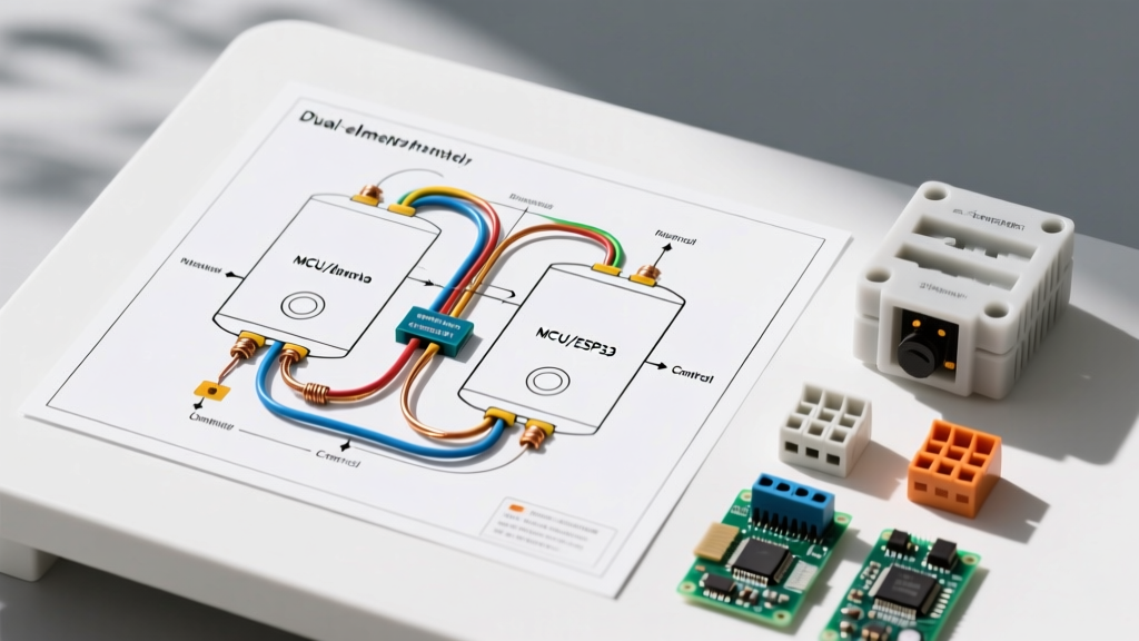
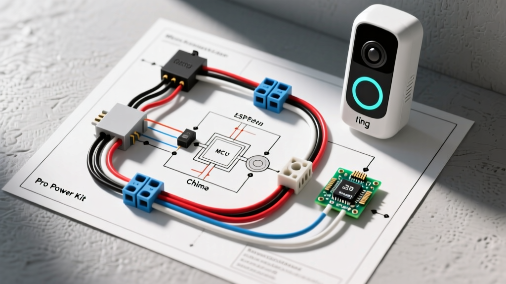
Most DIY enthusiasts and small engine technicians view the lawn mower ignition switch merely as a simple on/off toggle for the engine. However, from a modern Panel & Breaker Guide perspective, the ignition switch is actually the primary logic gate and master relay trigger for the mower's entire low-voltage DC distribution panel. In contemporary riding mowers and zero-turn radii (ZTR) machines from brands like John Deere, Toro, and Husqvarna, the ignition switch routes battery voltage to secondary fuse blocks, safety interlock modules, and high-amperage inline circuit breakers.
Understanding the wiring diagram for lawn mower ignition switch configurations requires looking beyond the key cylinder. You must trace how the switch interfaces with the main power distribution panel, manages overcurrent protection, and triggers the starter solenoid relay. A standard 12V DC mower electrical system relies on precise wire gauging and strategic breaker placement to prevent catastrophic harness fires, especially when routing power near high-heat exhaust manifolds and moving PTO (Power Take-Off) components.
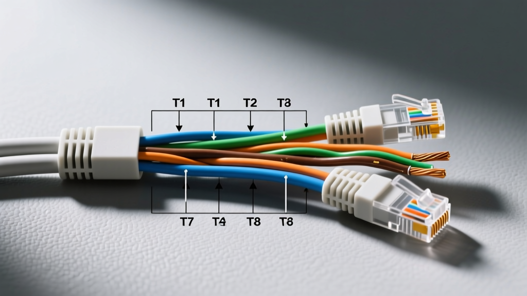
Terminal Pinout Matrix: 5-Prong vs. 6-Prong Configurations
When replacing a faulty switch or designing a custom fuse panel layout, identifying the correct terminal mapping is critical. The industry standard relies on lettered spade connectors. Below is the definitive matrix for the most common OEM replacement switches, such as the Oregon 33-315 (5-prong) and Rotary 13780 (6-prong).
| Terminal | Function | Typical Wire Color | Min. Gauge (AWG) | Panel / Breaker Connection |
|---|---|---|---|---|
| B | Battery (Main 12V+ Feed) | Red | 10 AWG | Direct from Main 30A Thermal Breaker or Maxi-Fuse |
| S | Starter Solenoid Trigger | Yellow / Red-White | 14 AWG | Protected by 10A ATO Blade Fuse on Secondary Panel |
| I | Ignition / Accessory Power | Purple / Brown | 14 AWG | Feeds Main Fuse Block (Lights, Hour Meter, ECU) |
| G | Ground (Chassis) | Black | 14 AWG | Common Ground Bus Bar on Fuse Panel |
| M | Magneto Kill (Engine Ground) | Black / White | 16 AWG | Routed to Safety Interlock Module or Direct Coil |
| L | Lighting Circuit (6-Prong Only) | Blue / Green | 14 AWG | Feeds 15A Lighting Relay or Dedicated Fuse Block |
Deep Dive: Main Feeds and Overcurrent Protection
The B (Battery) terminal is the most critical junction in the mower's electrical system. It carries the full amperage load required by the accessory panel and the starter solenoid trigger circuit. According to Briggs & Stratton Official Support guidelines and standard small engine electrical practices, this feed must never be run directly from the battery without overcurrent protection.
- Main Breaker Integration: A 30A Type 1 (Auto-Reset) thermal circuit breaker, such as the Littelfuse 1810 series (typically $12-$18), should be installed within 6 inches of the battery positive terminal. This protects the 10 AWG SAE J1128 GXL wire running to the ignition switch's 'B' terminal from dead-short fires.
- Accessory Panel Feed: When the key is turned to the 'Run' position, the I (Ignition) terminal energizes the main accessory fuse block. This panel typically houses 5A to 15A ATO/ATC blade fuses protecting the PTO clutch relay, fuel solenoid, and electronic control modules (ECMs).
Integrating the Ignition Switch with the Safety Interlock Panel
Modern mowers do not simply ground the magneto coil directly through the key switch to kill the engine. Instead, the M (Magneto) terminal interfaces with a solid-state Safety Interlock Module (a mini logic panel). This module monitors the seat switch, brake pedal switch, and PTO engagement switch.
If the operator leaves the seat while the PTO is engaged, the interlock module grounds the 'M' circuit, killing the engine instantly. When wiring a replacement switch, failing to route the 'M' terminal through this safety panel—and instead grounding it directly to the chassis—will bypass critical operator-presence safety features, a severe violation of Outdoor Power Equipment Institute (OPEI) safety standards.
Step-by-Step: Voltage Drop Testing at the Switch and Panel
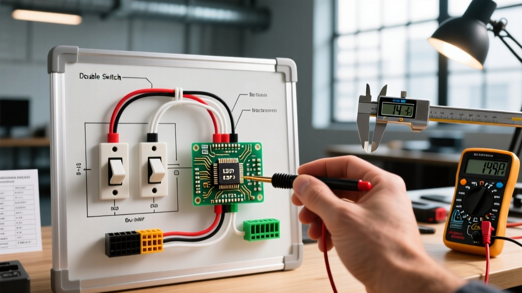
Before replacing a suspected faulty ignition switch or tearing into the fuse panel, perform a voltage drop test to identify high-resistance connections. A healthy switch and panel bus should exhibit minimal voltage loss under load.
- Prepare the Multimeter: Set your digital multimeter (DMM) to DC Volts. Ensure the mower battery is fully charged (reading 12.6V+ at rest).
- Test the Main Feed (B Terminal): Place the red probe on the battery positive post and the black probe on the 'B' terminal spade on the back of the ignition switch. Have an assistant turn the key to 'Start'. A reading above 0.2V indicates corrosion on the main breaker lugs or a failing 10 AWG crimp.
- Test the Solenoid Trigger (S Terminal): Place the red probe on the 'B' terminal and the black probe on the 'S' terminal. Turn the key to 'Start'. You should see full battery voltage (minus the 0.2V drop). If voltage is present but the starter doesn't crank, the fault lies downstream at the starter solenoid relay or its associated 10A panel fuse.
- Inspect the Ground Bus: Measure between the switch casing (if metal) or the 'G' terminal and the battery negative post. Any reading above 0.1V indicates a poor connection at the panel's common ground bus bar.
Critical Warning: Never bypass a blown blade fuse on the accessory panel by wrapping it in foil or installing a higher-amp fuse (e.g., replacing a 10A fuse with a 20A). The wiring harness from the ignition switch to the PTO relay is typically 16 AWG, rated for a maximum of 10-12 amps. Upsizing the fuse will melt the harness insulation before the main 30A breaker trips, resulting in a catastrophic chassis fire.
Common Failure Modes at the Panel-Switch Junction
When diagnosing electrical gremlins, look for these specific failure modes where the ignition switch meets the distribution panel:
- Spade Connector Fatigue: The female spade connectors on the wiring harness can stretch over time due to thermal cycling. This creates a loose fit on the switch terminals, leading to micro-arcing. The resulting heat melts the plastic switch housing, fusing the internal wafers and preventing the key from turning.
- Thermal Breaker Nuisance Tripping: If the main 30A inline breaker trips only when the PTO clutch engages, the issue is rarely the ignition switch itself. Instead, the PTO clutch air gap has likely widened beyond the 0.018-inch specification, causing it to draw excessive amperage (spiking above 4A) and overloading the shared accessory panel circuit.
- Water Intrusion in the Fuse Block: Mowers stored outdoors frequently suffer from water ingress in the accessory panel. Corrosion builds up on the ATO fuse blades, creating a voltage drop that starves the fuel solenoid of the 12V required to hold the main jet open, causing the engine to surge or stall despite a perfectly functioning ignition switch.
Wire Gauge Selection & Routing Best Practices
When rebuilding a mower's ignition and panel harness, always use SAE J1128 GXL (cross-linked polyethylene) wire rather than standard PVC-jacketed wire. GXL wire features a thinner, harder insulation that withstands the 125°C (257°F) ambient temperatures found near the engine block and exhaust routing. Use adhesive-lined heat shrink (3:1 shrink ratio) on all ring and spade terminal crimps to prevent moisture wicking into the copper strands, which causes green corrosion (copper oxide) and subsequent voltage drops at the fuse panel inputs.
Authoritative References
For further reading on small engine electrical safety, overcurrent protection standards, and OEM wiring schematics, consult the following resources:
- Briggs & Stratton Official Support & Troubleshooting Guides - Comprehensive manuals on engine electrical systems and safety interlock logic.
- Outdoor Power Equipment Institute (OPEI) - Industry standards for operator-presence control systems and safety certifications.
- Littelfuse Circuit Protection - Technical datasheets for automotive ATO/ATC fuses and Type 1/Type 2 thermal circuit breakers used in DC power distribution panels.