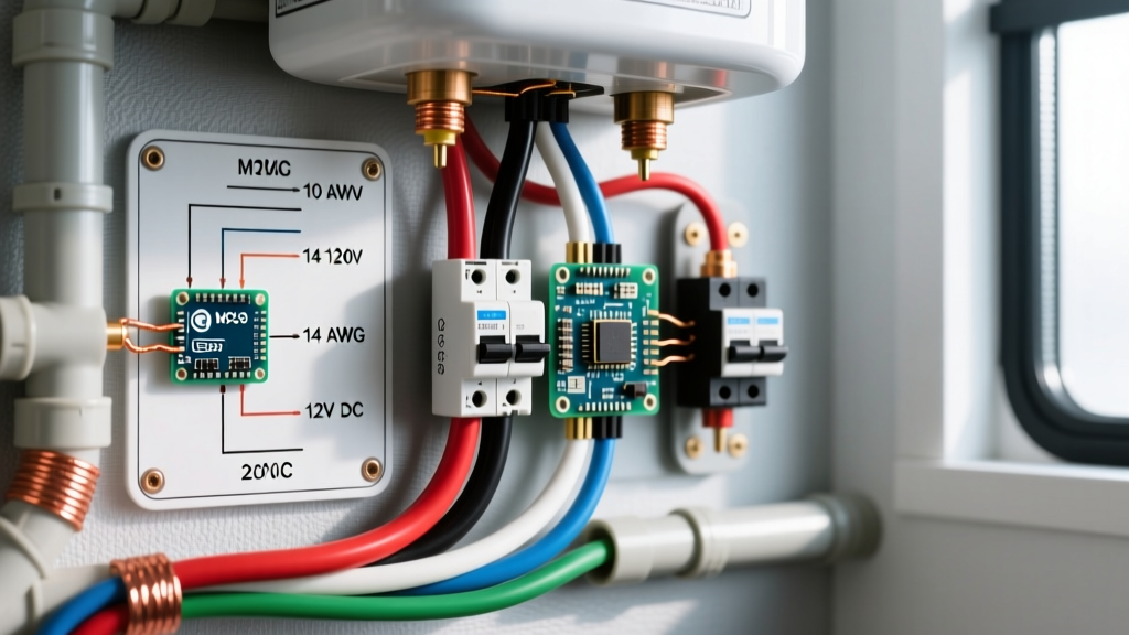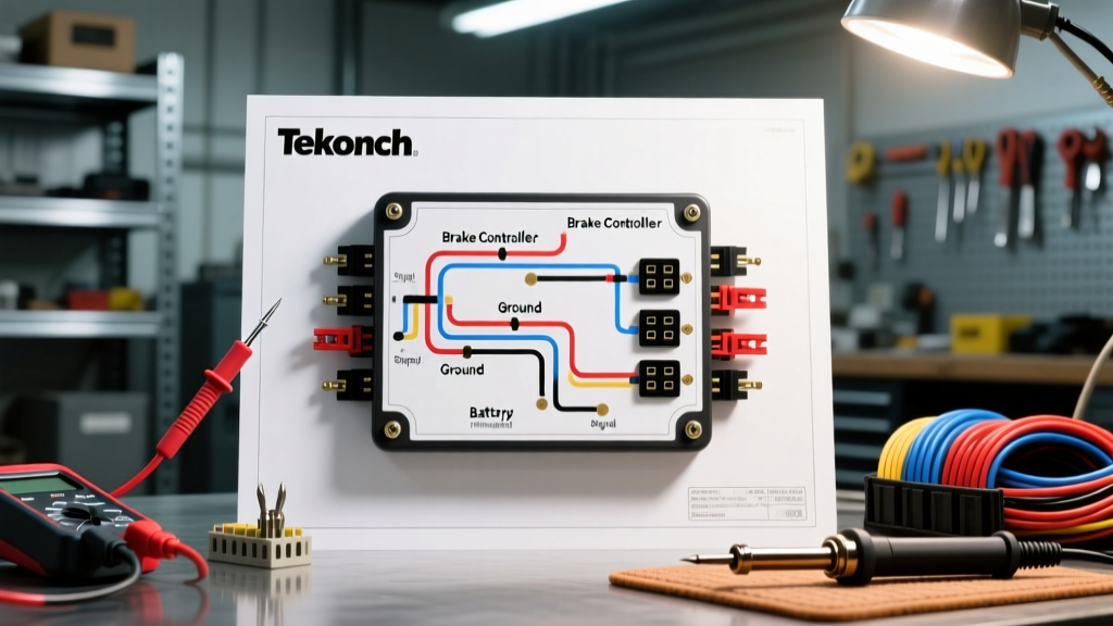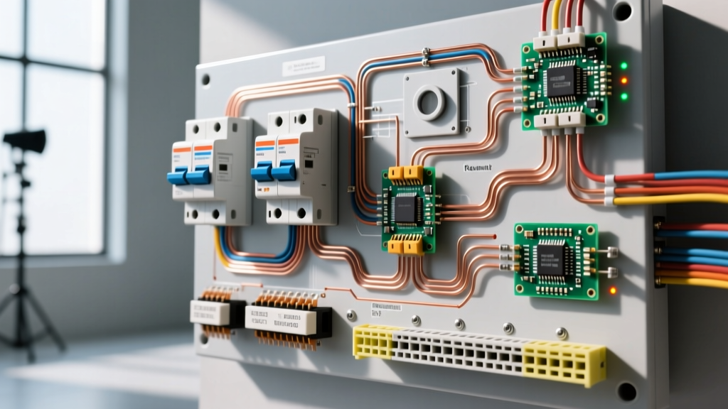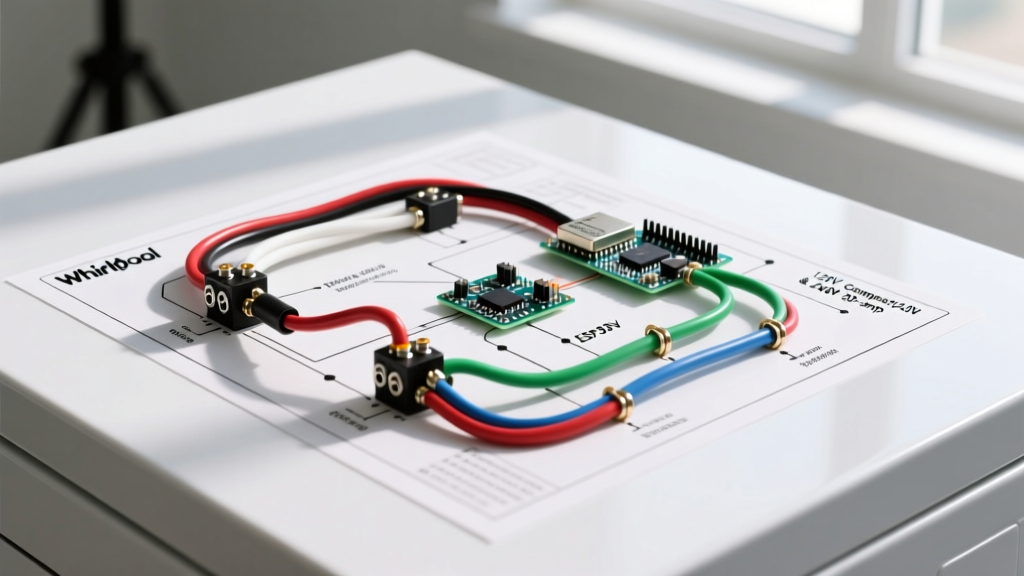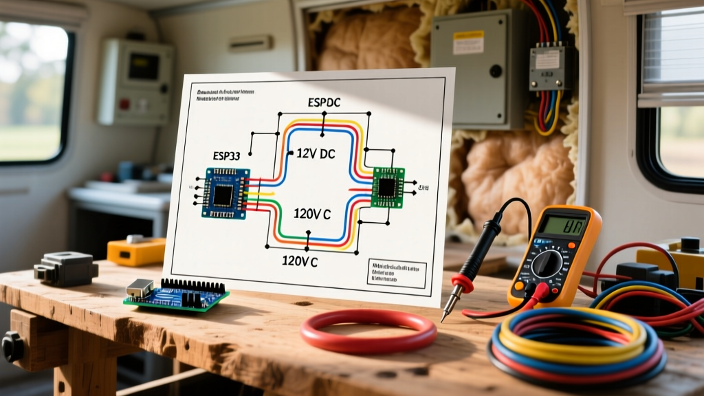

CRITICAL SAFETY WARNING: Mobile home electric furnaces operate on 240VAC lethal circuits and 120VAC blower circuits. Always disconnect all main power sources at the breaker panel and utilize a Lockout/Tagout (LOTO) procedure before opening the control box. Verify zero voltage with a CAT III or CAT IV multimeter before touching any terminals.
Core Architecture of Coleman EB and Presidential Series Furnaces
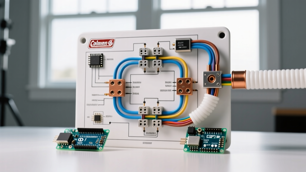
Understanding a Coleman mobile home electric furnace wiring diagram requires recognizing the split-voltage architecture inherent to manufactured housing HVAC systems. Unlike standard residential gas furnaces, Coleman electric models (such as the widely installed EB15B, EB20B, and Presidential 3400 series) rely entirely on high-wattage resistance heating elements. These elements draw massive current, necessitating a robust 240VAC supply, while the control circuit and blower motor operate on 120VAC and 24VAC, respectively.
The control box serves as the nerve center. It houses the 24V step-down transformer, the blower relay, the auto-reset and manual-reset limit switches, and the crucial time-delay sequencers. When a technician or DIYer references the wiring schematic located on the inside of the blower compartment door, they are looking at a logic map designed to stagger the engagement of heating elements to prevent catastrophic voltage drops and breaker trips.
24V Control Circuit and Thermostat Terminal Mapping
The low-voltage control circuit originates from a 40VA to 75VA step-down transformer (typically 240V primary to 24V secondary). The thermostat acts as a series of switches directing this 24VAC to specific relays and sequencer coils. Below is the standard terminal mapping for Coleman mobile home units interfacing with standard 5-wire or 6-wire thermostat setups.
| Terminal ID | Wire Color (Standard) | Function & Voltage | Internal Destination |
|---|---|---|---|
| R / Rc / Rh | Red | 24VAC Hot (Power) | Transformer Secondary (Hot) |
| W | White | Heat Call | Sequencer Coils (via Limit Switches) |
| G | Green | Blower Fan Call | Blower Relay Coil |
| Y | Yellow | Cooling Call (if Heat Pump/AC) | Contactor Coil (External Condenser) |
| C | Blue / Black | 24VAC Common | Transformer Secondary (Common) |
| E | Orange / Brown | Emergency Heat | Bypasses Heat Pump, Direct to Elements |
The Sequencer Logic: Preventing Inrush Current
The most misunderstood component on the Coleman wiring diagram is the sequencer (often manufactured by Honeywell or White-Rodgers for Coleman). If a 15kW or 20kW electric furnace engaged all heating elements simultaneously, the inrush current would instantly trip the main branch breakers and cause severe voltage sag across the mobile home's electrical panel.
Sequencers use a bimetallic switch actuated by a small 24V heater coil. When the thermostat calls for heat (W terminal energized), 24V is sent through the manual-reset limit switch, then through the auto-reset limit switches, and finally to the sequencer coils.
- Stage 1 (0-5 Seconds): The first sequencer coil heats up. Its normally-open (NO) contacts close, sending 240V to the first bank of heating elements. Simultaneously, a secondary set of contacts closes to energize the 120V blower motor.
- Stage 2 (10-15 Seconds): The second sequencer coil heats up, closing its contacts and sending 240V to the second bank of elements.
- Stage 3 (15-20 Seconds): On larger units (like the 20kW EB20B), a third sequencer may engage the final element bank.
Testing Sequencer Terminals with a Multimeter
When troubleshooting a 'no-heat' condition, do not immediately replace the heating elements. Test the sequencer first. Set your multimeter to Ohms (Ω). Disconnect power and isolate the sequencer coil terminals. A healthy Coleman/Honeywell sequencer coil will read between 15 and 25 ohms. If you read infinite resistance (OL), the internal coil wire is broken, and the sequencer must be replaced. Next, test the high-voltage contacts (H1/H2 for elements, M1/M2 for blower). With power off, these should read OL (open). When 24V is applied to the coil, they should drop to near 0.0 ohms (closed).
HUD Compliance and NEC Article 550 Grounding Rules
Wiring a mobile home furnace differs fundamentally from site-built homes due to strict federal and national codes governing manufactured housing. According to the U.S. HUD Manufactured Home Construction and Safety Standards (24 CFR Part 3280), the electrical system must maintain a strict separation between the neutral (grounded conductor) and the equipment grounding conductor.
Furthermore, the NFPA 70 National Electrical Code (NEC) Article 550 dictates specific branch circuit requirements for mobile homes. The Coleman furnace must be fed by a dedicated 4-wire circuit (two hots, one neutral, one ground) from the exterior disconnect or main panel. The furnace chassis must be bonded to the equipment grounding conductor, never to the neutral bus. Improper bonding is a leading cause of stray voltage shocks in older mobile homes and will cause immediate failure of modern GFCI/AFCI protection devices upstream.
Wire Gauge and Dual-Circuit Breaker Sizing Matrix
Mobile home electric furnaces frequently utilize dual branch circuits to distribute the massive electrical load. A 20kW furnace draws approximately 83.3 Amps at 240V, which exceeds the capacity of a single standard residential breaker. Coleman designs these units with split-terminal blocks to accept two separate 240V feeds. Always consult the U.S. Department of Energy HVAC Guidelines and local codes before upgrading wire sizes.
| Furnace kW Rating | Total Amp Draw (240V) | Circuit Configuration | Min. Copper Wire Gauge (THHN) | Breaker Size (Per Circuit) |
|---|---|---|---|---|
| 10 kW | 41.6 A | Single Circuit | 8 AWG | 50 A |
| 15 kW | 62.5 A | Single or Split | 6 AWG (Single) / 10 AWG (Split) | 70 A (Single) / 35 A (Split) |
| 20 kW | 83.3 A | Dual Split Circuit | 8 AWG (Per Circuit) | 50 A (Per Circuit) |
Step-by-Step Diagnostic Workflow for Blower Failures
If the heating elements engage but the blower motor fails to push air through the ductwork, the limit switches will eventually trip to prevent a fire. Follow this diagnostic sequence:
- Verify the Blower Relay: When the thermostat calls for fan (G terminal), listen for an audible click from the blower relay in the control box. If no click, test for 24VAC across the relay coil. If voltage is present but the relay doesn't pull in, replace the relay.
- Check the Sequencer Motor Contacts (M1/M2): The blower motor often receives its 120V hot leg through the first sequencer's M1/M2 contacts. If the sequencer coil is functional but the M1/M2 contacts are pitted or burnt, the blower will not receive power. Bypass the M1/M2 contacts temporarily with a jumper wire (with extreme caution) to verify if the motor runs.
- Test the Run Capacitor: Coleman furnaces typically use a Fasco or Century 1/3 HP, 1100 RPM blower motor with a 5 MFD or 7.5 MFD run capacitor. Use a multimeter with capacitance testing. A reading more than 6% below the rated MFD indicates a failing capacitor, which will cause the motor to hum, overheat, and trip its internal thermal overload.
- Inspect the Auto-Reset Limit Switches: Located on the heater box assembly, these bimetallic disc switches open if the temperature exceeds 175°F to 200°F. If the blower failed previously, these may be stuck open. Test for continuity; replace if open.
Frequently Asked Questions
Why does my Coleman furnace trip the breaker after 15 seconds?
This is a classic symptom of a stuck sequencer or a shorted heating element. If the second or third sequencer's high-voltage contacts weld themselves shut, the elements remain energized continuously, or multiple stages engage simultaneously, bypassing the time-delay logic and causing an immediate overcurrent event. Test each element for continuity to ground; any reading below 100kΩ indicates a compromised element sheath leaking current to the chassis.
Can I use a standard residential thermostat with my Coleman mobile home furnace?
Yes, but you must ensure the thermostat supports multi-stage electric heat or is configured specifically for 'Electric' in the installer setup menu. If configured for 'Gas', the thermostat will not energize the blower relay during a heat call, relying instead on a fan-limit switch which most modern Coleman sequencer setups do not utilize in the same manner. This will result in heat without airflow, tripping the high-limit switches.
What is the purpose of the orange 'E' wire on the thermostat diagram?
The 'E' terminal is designated for Emergency Heat. In a mobile home equipped with a Heat Pump and a Coleman electric furnace as the auxiliary/emergency backup, energizing the 'E' terminal bypasses the heat pump's outdoor compressor entirely and sends a direct 24V signal to the furnace sequencers. This is used when outdoor temperatures drop below the heat pump's efficient operational threshold (usually below 25°F) or if the outdoor unit fails.