
The Critical Role of ATS in Backup Power Systems
When utility power fails, an Automatic Transfer Switch (ATS) is the mechanical and electrical brain that seamlessly transitions your critical loads to a backup generator. However, interpreting a wiring diagram for ATS is not just about making connections; it is a rigorous exercise in life-safety and code compliance. Improper wiring can lead to catastrophic utility backfeeding, which endangers line workers, or cause objectionable neutral currents that trip ground-fault protection and start electrical fires.
As electrical inspectors enforce the latest 2026 NEC adoption cycles across municipalities, understanding the nuanced differences between service-entrance-rated equipment, separately derived systems (SDS), and switched neutrals is mandatory. This guide dissects the standard wiring diagram for ATS installations, focusing heavily on National Electrical Code (NEC) compliance, precise torque specifications, and advanced troubleshooting protocols.
Decoding the Standard Wiring Diagram for ATS
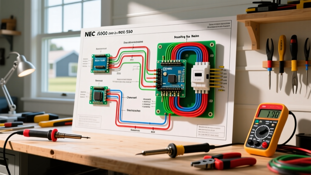
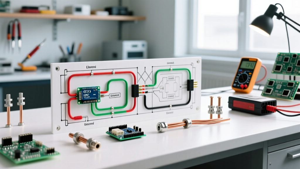
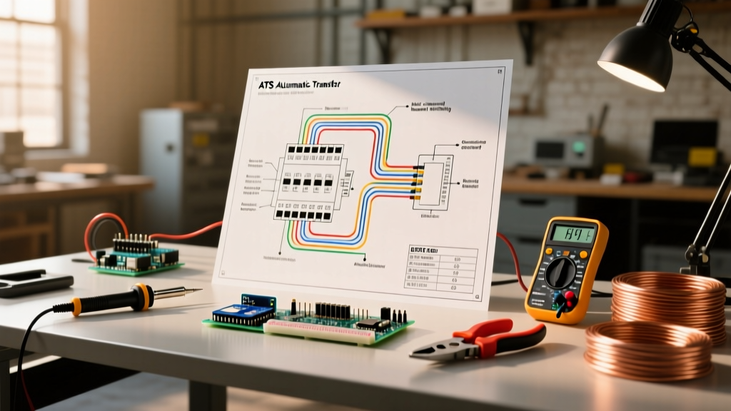
A comprehensive ATS wiring diagram is divided into two primary circuits: the power circuit and the control circuit. Misinterpreting the control circuit is the most common cause of commissioning failures.
1. The Power Circuit (Utility, Generator, and Load)
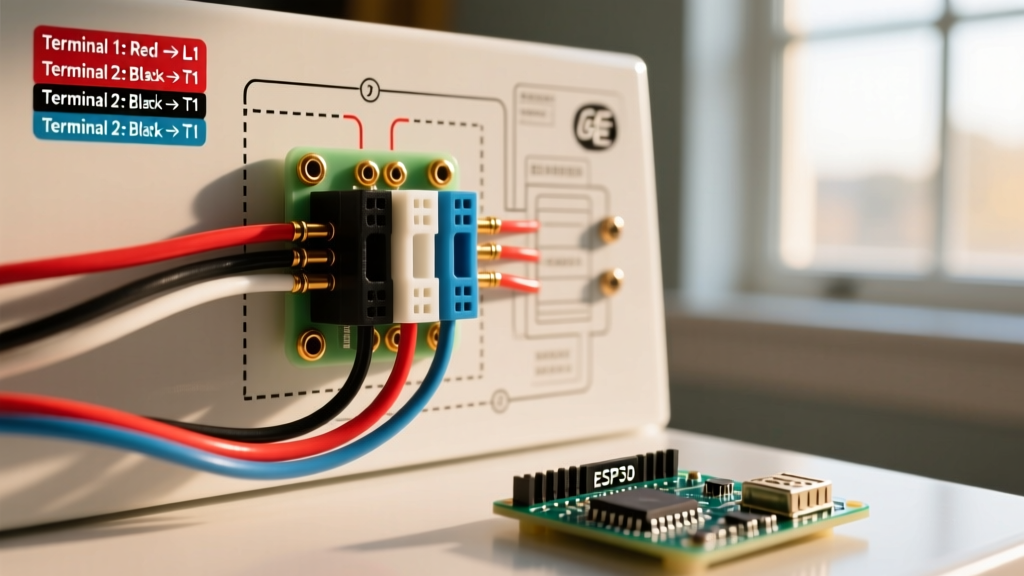
The power circuit handles the high-amperage AC current. In a standard 200-amp residential or light commercial diagram, you will see three main lugs per phase (L1, L2) plus the neutral (N) and ground (G). The diagram will explicitly show the mechanical interlock—a physical barrier preventing the utility and generator contactors from closing simultaneously. This interlock is a strict requirement under NFPA NEC Article 700.5 for emergency systems to prevent cross-connection.
2. The Control Circuit (Sensing and Logic)
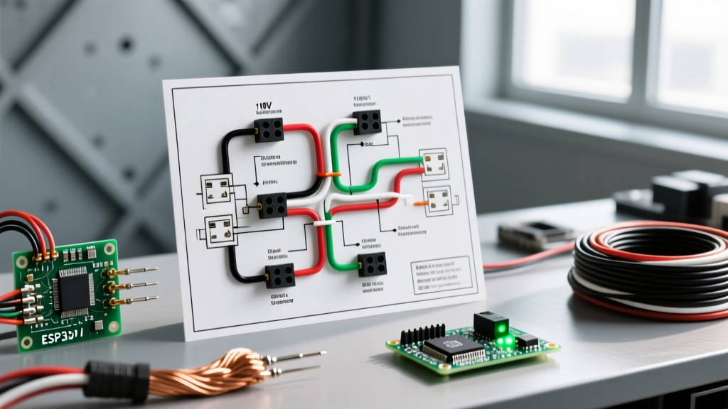
The control circuit operates on a lower voltage (typically 120VAC derived from the utility line, or 24VDC from an internal battery). Key diagram nodes include:
- Utility Sensing Relay: Monitors the utility voltage. If it drops below 85% of nominal (e.g., 204V on a 240V system) for a preset time delay (usually 1 to 3 seconds), it initiates the transfer sequence.
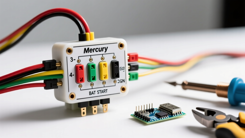
- Generator Start Signal: A two-wire dry contact closure that signals the generator's engine control module (ECM) to crank.
- Transfer Timer (TDEN): Time Delay on Emergency Normal. Once the generator reaches nominal voltage and frequency (usually 60Hz ± 2%), the diagram routes power to the transfer solenoid, shifting the load.
The Neutral Dilemma: 3-Pole vs. 4-Pole ATS
The most heavily scrutinized aspect of any ATS wiring diagram by electrical inspectors is the neutral connection. This is where code violations most frequently occur, specifically regarding NEC Article 250.6 (Objectionable Current).
Code Alert: If your generator features a bonded neutral (the neutral is physically tied to the generator frame ground), it is NOT a Separately Derived System (SDS) until that bond is removed or the neutral is switched at the ATS. Parallel neutral paths will cause current to flow on the equipment grounding conductor, violating NEC 250.6 and potentially causing lethal touch potentials.
When to Use a 3-Pole (Non-Switched Neutral) Diagram
A 3-pole ATS wiring diagram only switches the hot legs (L1, L2). The neutral is hard-bussed through the switch and never breaks. You must use a 3-pole diagram only if the generator's neutral-to-ground bonding strap has been physically removed, and the system is wired as a Separately Derived System (SDS) per NEC 250.20 and 250.30. In this scenario, a new grounding electrode system must be established at the generator.
When to Use a 4-Pole (Switched Neutral) Diagram
If you are installing a portable generator connection, or if the manufacturer's warranty prohibits removing the neutral bond (common in many residential air-cooled units), you must use a 4-pole ATS. The wiring diagram for a 4-pole ATS shows the neutral passing through a dedicated, mechanically interlocked fourth pole. This completely isolates the utility neutral from the generator neutral, satisfying code without altering the generator's internal SDS status.
Service Entrance vs. Non-Service Entrance Ratings
Before pulling a single wire, verify if your ATS diagram denotes a Service Entrance (SE) or Non-Service Entrance (Branch) rated switch. This dictates where the main bonding jumper is located.
| Feature | Service Entrance (SE) Rated ATS | Non-Service Entrance ATS |
|---|---|---|
| Location | First point of disconnect (replaces main panel breaker) | Downstream of the main utility disconnect |
| Grounding Bond | Includes a factory-installed main bonding jumper (Neutral to Ground) | Bonding jumper MUST be removed; relies on upstream panel bond |
| Ground Fault Protection | Required if upstream service is >1000A (NEC 230.95) | Not required at the ATS level |
| Common Models | ASCO 300 Series, Generac RXSW200A3 (SE) | Eaton DTSC200, Generac RXSW200A3 (Non-SE) |
According to ASCO Power Technologies, installing a non-SE rated switch at the service drop without an upstream disconnect is a direct violation of NEC 230.70, resulting in an immediate red-tag from the inspector.
Step-by-Step Wiring & Safety Verification Protocol
Following the diagram is only half the battle. As highlighted by OSHA Electrical Safety Guidelines, arc flash and electrocution hazards during ATS commissioning are severe. Adhere to this strict protocol:
Phase 1: Lockout/Tagout (LOTO) and Preparation
- Disconnect and lock out the utility main breaker.
- Disconnect the generator starting batteries to prevent auto-cranking.
- Verify zero energy state using a CAT IV rated multimeter on all utility and generator lugs.
Phase 2: Termination and Torque Specifications
NEC 110.14(D) mandates that all terminations be torqued to the manufacturer's specifications using a calibrated tool. Hand-tightening leads to high-resistance connections, which will thermally fail under load.
- 2/0 AWG Copper (200A Residential): Typically requires 250 in-lbs (inch-pounds) of torque on the mechanical lug screws.
- Control Wiring (14-18 AWG): Typically 12 to 15 in-lbs. Over-torquing control wires will strip the terminal block, causing intermittent sensing failures.
Phase 3: Insulation Resistance (Megger) Testing
Before applying power, perform a Megger test at 1000V DC across the utility and generator phases to ground. A reading of less than 1 Megohm indicates compromised wire insulation or a missed grounding fault inside the conduit. Never Megger the ATS control board; disconnect the logic harness first to avoid destroying the solid-state sensing relays.
Troubleshooting Code Violations & Failure Modes
Even when a wiring diagram for ATS is followed, edge cases and environmental factors can introduce dangerous failure modes.
Failure Mode 1: Utility Backfeed via Welded Contacts
If the utility contactor inside the ATS experiences a massive short circuit during transfer, the magnetic force can physically weld the contacts shut. If the generator then starts and the generator contactor closes, you have a direct phase-to-phase fault between the utility and the generator. Prevention: Modern diagrams incorporate auxiliary contact switches that provide feedback to the logic board. If the logic detects a welded contact, it will physically block the generator contactor from closing and trigger a hard alarm.
Failure Mode 2: Nuisance Tripping on Generator Ground Faults
If a 3-pole ATS is used with a bonded-neutral generator, the neutral current will split between the neutral wire and the equipment grounding conductor. If the generator is equipped with a Ground Fault Circuit Interrupter (GFCI) or Ground Fault Protection of Equipment (GFPE), this parallel path will be read as a ground fault, tripping the generator offline during an outage. Solution: Swap to a 4-pole switched neutral ATS or remove the generator bonding strap and install a dedicated grounding electrode per NEC 250.30.
Frequently Asked Questions (FAQ)
Can I wire my own ATS without an electrician?
No. Wiring an ATS involves working inside the main service panel and handling utility-side conductors that remain live even when the main breaker is off. Only licensed electrical contractors should perform this work to comply with local AHJ (Authority Having Jurisdiction) permitting and NEC codes.
What size wire is needed for a 200-amp ATS?
For a 200-amp residential ATS, the NEC requires a minimum of 2/0 AWG copper or 4/0 AWG aluminum for the hot and neutral conductors, assuming a 75°C termination rating. The equipment grounding conductor must be a minimum of 6 AWG copper.
Why does my generator start but the ATS won't transfer?
Check the wiring diagram's 'Transfer Enable' circuit. The ATS logic board will not transfer the load if the generator frequency is unstable (outside 58-62Hz) or if the voltage is outside the acceptable window (usually 216V to 264V for a 240V system). A faulty generator governor or AVR (Automatic Voltage Regulator) is often the culprit, not the ATS itself.