
Decoding the 1965 Mustang Electrical Architecture
The 1965 Ford Mustang is an undisputed automotive icon, but its original electrical system was designed for a much simpler era. With a basic 12-volt system, a generator (or early low-output alternator), and minimal accessory loads, the factory wiring was adequate for 1965 but is often dangerously undersized for modern restomods. Whether you are performing a concours-correct restoration or integrating modern fuel injection, understanding how to read and apply a wiring diagram for 1965 Mustang applications is the foundation of a safe, reliable build.
This comprehensive reference guide breaks down the exact wire gauge specifications, decodes the OEM Ford color code matrix, and highlights critical failure modes—specifically the infamous ammeter fire risk—that every Mustang builder must address.
Safety Protocol: Before probing any circuit or modifying the harness, always disconnect the negative battery cable at the chassis ground. On a 1965 Mustang, the main battery feed is constantly hot all the way to the ignition switch and the dash ammeter. A short circuit here bypasses the fuse panel entirely.
Navigating the Wiring Diagram for 1965 Mustang Models
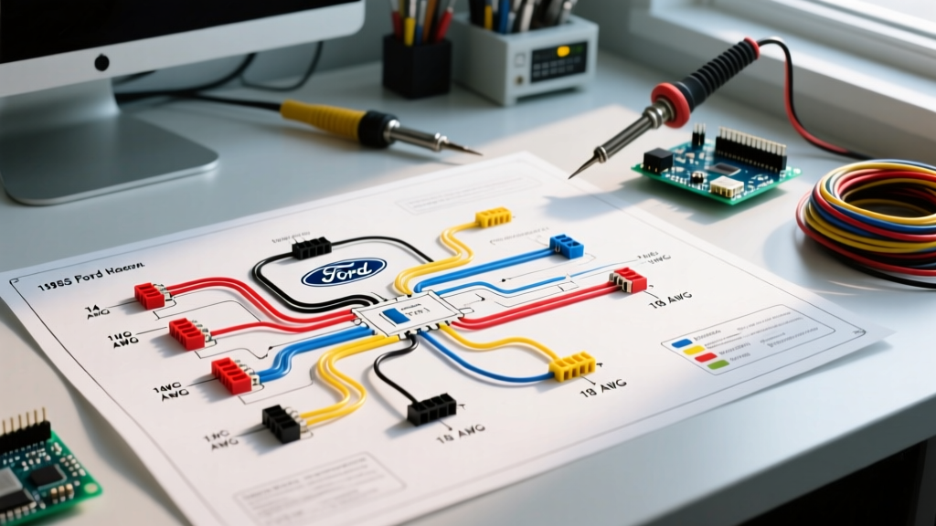
A standard factory wiring diagram for the 1965 Mustang is divided into three primary sub-harnesses: the main dash harness, the engine feed harness, and the forward lighting harness. When reading authoritative guides on automotive schematics, you will notice Ford utilized a specific logic for circuit routing that differs slightly from GM and Chrysler vehicles of the same era.
OEM Reproduction vs. Modernized Aftermarket Harnesses
Before cutting or splicing, you must decide on your harness strategy. Your wiring diagram will change drastically depending on this choice:
- OEM Reproduction (e.g., M&H Electrical Fabricators): Costs between $250 and $350. Features the exact 8-to-10 circuit count, cloth-braided PVC insulation, and factory color codes. Ideal for concours judging but lacks circuits for modern EFI, electric fans, or high-power audio.
- Modernized Aftermarket (e.g., American Autowire Classic Update or Painless Performance): Costs between $450 and $750. Features 18 to 21 circuits, modern ATO blade fuses, XLPE (cross-linked polyethylene) high-temp insulation, and dedicated relays for headlights. The wiring diagram for these kits uses industry-standard GM/Delphi color codes rather than 1965 Ford codes.
1965 Mustang Wire Gauge Specifications
Wire gauge selection is not arbitrary; it is dictated by the amperage draw and the physical length of the wire run to prevent excessive voltage drop. According to the SAE J1128 standard for low-tension primary cable, modern insulation can handle higher temperatures, but the copper cross-section must still be sized for the current. Below is the definitive wire gauge reference for a 1965 Mustang.
| Circuit / Component | OEM 1965 Gauge | Recommended Restomod Gauge | Max Amperage (Continuous) |
|---|---|---|---|
| Battery to Starter Solenoid | 6 AWG | 4 AWG or 2 AWG | 250A+ (Cranking surge) |
| Alternator Main Charge Wire | 10 AWG | 6 AWG or 4 AWG | 100A - 140A |
| Headlight Feed (from switch) | 14 AWG | 12 AWG (with relays) | 15A - 20A |
| Ignition Switch to Coil/Ballast | 16 AWG | 14 AWG | 5A - 8A |
| Tail Lights / Brake Lights | 18 AWG | 16 AWG | 5A - 10A |
| Instrument Panel Illumination | 18 AWG | 18 AWG (LED conversion) | 2A - 4A |
| Horn Relay Feed | 14 AWG | 12 AWG | 15A |
Voltage Drop Considerations for 6V to 12V Swaps and Halogen Upgrades
Many early 1965 models or transitional builds suffer from dim headlights. If you upgrade from OEM 45-watt sealed beams to 65-watt H4 halogen conversions without upgrading the 14 AWG headlight feed wire, you will experience a severe voltage drop. Over a 12-foot run, 14 AWG wire pushing 11 amps will drop nearly 0.8 volts. At the bulb, you will only see 11.2V, resulting in a 20% loss of light output and excessive heat in the headlight switch. The fix: Use the factory headlight switch only to trigger a 30A Bosch-style relay mounted near the radiator support, feeding the headlights directly from the battery via 10 AWG wire.
Ford Standard Color Code Reference Matrix
Ford's 1965 color code system utilized a solid base color with a contrasting tracer (stripe). When reading an OEM wiring diagram for 1965 Mustang vehicles, you will see abbreviations. Understanding these is critical for matching circuits during a restoration.
Common Ford Color Abbreviations
- BK: Black (Primary Ground / Chassis)
- R: Red (Constant Battery Hot / Unfused)
- Y-BK: Yellow with Black Tracer (Headlight feed from dimmer switch)
- G-RD: Green with Red Tracer (Tail light feed)
- BL-RD: Blue with Red Tracer (Instrument panel illumination)
- O-BK: Orange with Black Tracer (Accessory / Radio feed)
- W-BK: White with Black Tracer (Neutral safety switch / Backup lamps)
- G-O: Green with Orange Tracer (Right hand turn signal / brake)
- Y-O: Yellow with Orange Tracer (Left hand turn signal / brake)
Note: If you are using a Painless Performance or American Autowire harness, discard this matrix. Modern aftermarket kits use standard GM color codes (e.g., Purple for headlights, Brown for taillights, Dark Green for right rear, Yellow for left rear).
Critical Troubleshooting: The 'Melting Ammeter' Failure Mode
This is the most dangerous electrical flaw in the 1965 Mustang and represents a massive information gap for novice builders. Unlike later models that used a shunt-type ammeter or an idiot light, the 1965 Mustang routes the entire output of the alternator through the dash-mounted ammeter and back to the starter solenoid.
The Failure Mechanism
The factory alternator produced a mere 38 to 45 amps. The factory 10 AWG charge wire and the internal shunt of the dash ammeter were sized for this load. Today, restorers frequently upgrade to a 1-wire, 100-amp alternator (such as a Powermaster 17294). When the electric cooling fans, fuel pump, and halogen lights pull 70 amps, that current is forced through the 50-year-old 10 AWG wire and the tiny ammeter shunt. The wire acts as a resistor, generating extreme heat. This routinely melts the dash harness insulation, destroys the printed circuit board, and causes under-dash electrical fires.
The Expert Solution: The Ammeter Bypass
- Disconnect the Battery: Remove the negative terminal.
- Isolate the Dash Harness: Unplug the original 10 AWG charge wire from the alternator and tape off the end. Do not let it touch ground.
- Run a New Charge Wire: Run a new continuous length of 6 AWG or 4 AWG primary wire directly from the alternator's output stud to the battery side of the starter solenoid (where the main battery cable connects).
- Install a Mega Fuse: Place a 125A ANL or Mega fuse inline on this new charge wire within 8 inches of the solenoid.
- Convert the Gauge: Swap the dash ammeter for a matching voltmeter, wiring it to a switched 12V source and a clean chassis ground.
By executing this bypass, you completely remove the high-amperage load from the dash, ensuring your wiring diagram for the 1965 Mustang remains safe under modern electrical loads.
Upgrading the Grounding System
The 1965 Mustang relies heavily on the engine block and sheet metal chassis for return paths. Poor grounds cause erratic gauge behavior, dim lights, and hard starting. When referencing your wiring diagram, ensure these specific ground straps are installed using braided copper or 4 AWG flexible welding cable:
- Engine Block to Firewall: Essential for dashboard gauges and the heater blower motor. Locate on the back of the cylinder head to the upper firewall.
- Engine Block to Chassis Frame: Required for the starter motor return path. Connect from the lower block mounting bolt to the front crossmember.
- Battery to Chassis: The negative battery cable must have a dedicated pigtail grounding directly to the inner fender apron, not just relying on the engine block ground.
Voltage Drop Testing Procedures
Do not rely on visual inspections to verify your wiring. Use a digital multimeter (DMM) to perform a voltage drop test. Set your DMM to DC Volts. Place the red probe on the positive battery post and the black probe on the component's positive terminal while the circuit is under load. A reading above 0.2V indicates excessive resistance in the wire or a corroded bulkhead connector. Repeat on the ground side (black probe on negative battery post, red probe on component housing). For optimal performance in a 1965 Mustang, total circuit voltage drop should not exceed 0.4V.
FAQ: 1965 Mustang Wiring Queries
Do I need a different wiring diagram if my 1965 Mustang has a factory GT package?
Yes. The 1965 GT Equipment Group introduced the 5-dial instrument cluster (including a mechanical oil pressure gauge and an ammeter) and auxiliary driving lights in the grille. The forward lighting harness and the main dash harness differ significantly from the standard Falcon-derived 3-dial cluster models.
Can I use the original 1965 headlight switch with modern LED headlights?
While LEDs draw significantly less current (often under 2 amps per bulb), the 1965 headlight switch contains an internal thermal circuit breaker designed for the heat generated by 10-amp halogen/sealed beam loads. With LEDs, the switch may not generate enough heat to keep the internal bimetallic strip engaged, causing the headlights to flicker or shut off intermittently. It is highly recommended to use the factory switch only as a low-amp trigger for external headlight relays.
Where can I find concours-correct wiring clips and connectors?
For OEM-style molded rubber bulkhead connectors, firewall grommets, and specific Ford terminal ends, the Mustang Club of America (MCA) technical resources and approved vendors like NPD (National Parts Depot) and CJ Pony Parts are the most reliable sources to ensure your harness matches the original factory assembly line specifications.