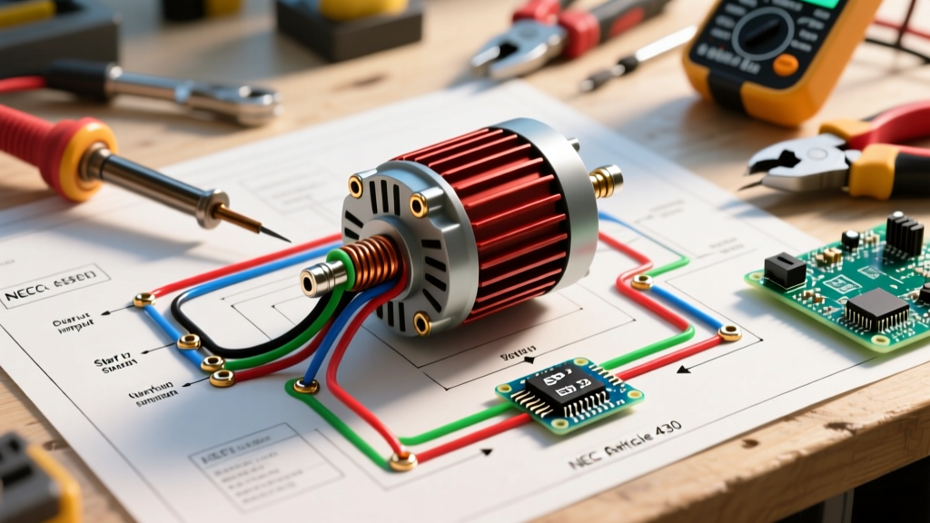

Pre-Installation Assessment & NEC Article 430 Compliance
Planning the installation of a single phase electric motor requires more than simply matching wire colors to terminals. Whether you are wiring a 1/2 HP capacitor-start motor for a residential HVAC blower or a 5 HP split-phase motor for an industrial air compressor, the foundation of a reliable system lies in rigorous pre-installation planning. In 2026, with copper prices averaging $0.65 per foot for 10 AWG THHN and advanced solid-state overload relays becoming the norm, optimizing your material list and circuit design is critical for both budget and safety.
The governing standard for motor circuits in the United States is National Fire Protection Association (NFPA 70), specifically NEC Article 430. Unlike standard branch circuits governed by Article 210, motor circuits have unique exceptions for overcurrent protection and conductor sizing due to the high inrush currents (Locked Rotor Amperage, or LRA) inherent to single phase electric motor wiring.
NEC 430.22(A) Continuous Duty: Conductors supplying a single motor used in a continuous duty application must have an ampacity of not less than 125% of the motor's Full-Load Current (FLC) as determined by NEC Table 430.248, not the nameplate rating.
Conductor Sizing & Overcurrent Protection Matrix
A common failure mode in DIY and commercial installations is sizing the branch circuit breaker based on the motor's nameplate Full-Load Amps (FLA). This inevitably leads to nuisance tripping during startup. Single phase electric motors typically draw 600% to 800% of their FLA for a few seconds during acceleration. Therefore, the branch circuit short-circuit and ground-fault protective device (breaker) must be sized to allow this inrush, while the overload relay protects the motor from sustained overcurrent.
Below is a planning matrix based on NEC Table 430.248 (FLC) and 430.52 (Maximum Breaker Sizing for Inverse Time Breakers). Note that while THHN wire is rated at 90°C, termination limits at standard breakers and motor starters typically restrict ampacity to the 75°C column.
| Motor HP | Voltage | NEC Table FLC | Min. Wire Size (THHN 75°C) | Max Inverse Time Breaker | Recommended Thermal Overload |
|---|---|---|---|---|---|
| 1/2 HP | 115V | 9.8A | 14 AWG | 15A | 6.3A - 8.0A |
| 1/2 HP | 230V | 4.9A | 14 AWG | 15A | 3.2A - 4.5A |
| 1 HP | 115V | 16.0A | 12 AWG | 40A | 11.0A - 14.0A |
| 1 HP | 230V | 8.0A | 14 AWG | 20A | 5.5A - 7.5A |
| 2 HP | 230V | 12.0A | 12 AWG | 30A | 8.5A - 11.0A |
| 3 HP | 230V | 17.0A | 10 AWG | 45A | 12.0A - 16.0A |
| 5 HP | 230V | 28.0A | 8 AWG | 70A | 20.0A - 26.0A |
Selecting the Right Motor Controller & Starter
For single phase electric motor wiring, you must choose between a manual motor starter and a magnetic contactor with an overload relay. Your choice depends on the application's duty cycle and remote-control requirements.
Manual Motor Starters
Ideal for localized, line-of-sight applications like bench grinders or small drill presses. A premium option is the Siemens 3RV2021-1DA10 Motor Protection Circuit Breaker (MPCB). Priced around $110-$130, it combines the short-circuit breaker and the thermal overload into a single DIN-rail mounted unit, saving significant panel space. It features an adjustable overload dial (2.2A to 3.2A) perfect for a 1/2 HP 230V motor.
Magnetic Contactors with Overload Relays
Required when the motor is controlled by a remote switch, thermostat, or PLC. A standard configuration pairs a Eaton C25DRA Definite Purpose Contactor (approx. $45) with a Siemens 3RU2116 Thermal Overload Relay (approx. $75). The control circuit (often 24VAC from a transformer) energizes the contactor coil (A1/A2 terminals), pulling in the main power contacts (L1/T1 and L2/T2) to start the motor. This setup isolates high-voltage single phase motor wiring from delicate low-voltage control logic.
Dual-Voltage Terminal Wiring: 115V/230V Configurations
Most fractional and integral horsepower single phase motors (1 HP and above) are dual-voltage, allowing them to operate on either 115V or 230V. According to National Electrical Manufacturers Association (NEMA MG 1) standards, running a dual-voltage motor at 230V is highly recommended. It halves the current draw, reduces voltage drop across long wire runs, and minimizes I²R heat generation in the windings.
A standard 8-lead dual-voltage single phase motor features a peckerhead (connection box) with terminals labeled T1 through T8. Here is the precise wiring sequence for the two main configurations:
High Voltage (230V) Wiring Sequence
In the 230V configuration, the two main run windings are wired in series.
- Link T4 and T8: Use a wire nut or terminal link to connect T4 and T8 together. This bridges the end of the first run winding to the start of the second.
- Link T5 and T7: Connect T5 and T7 together. This bridges the start winding circuit.
- Line 1 Connection: Connect your incoming L1 (Hot 1) to T1.
- Line 2 Connection: Connect your incoming L2 (Hot 2) to T2.
Low Voltage (115V) Wiring Sequence
In the 115V configuration, the two main run windings are wired in parallel to handle the doubled current.
- Group 1: Connect T1, T4, and T5 together.
- Group 2: Connect T2, T7, and T8 together.
- Line Connection: Connect incoming L1 (Hot) to Group 1, and incoming L2 (Neutral) to Group 2.
Real-World Failure Modes & Edge Cases
Even with perfect single phase electric motor wiring diagrams, field conditions introduce variables that cause premature failure. As highlighted in the Fluke Corporation Motor Troubleshooting Guide, thermal degradation is the primary killer of motor insulation. Here are specific edge cases to plan for:
- Capacitor Wiring Reversal: On Capacitor-Start/Capacitor-Run (CSCR) motors, the start capacitor is wired in series with the centrifugal switch, while the run capacitor is wired directly across the start and run windings. Swapping these will cause the start capacitor to explode within seconds of energization, as start capacitors are only rated for a 3-second duty cycle.
- Voltage Drop at the Peckerhead: NEC recommends a maximum 3% voltage drop for branch circuits. If you are wiring a 5 HP 230V motor located 150 feet from the panel, 8 AWG wire (while meeting NEC ampacity rules) will result in a 4.1% voltage drop. You must upsize to 6 AWG copper to maintain starting torque, which drops exponentially with voltage (Torque ∝ Voltage²).
- The "Ghost Voltage" Trap: When testing single phase motor circuits with a high-impedance digital multimeter (DMM), you may read 120V on a blown fuse or open breaker due to capacitive coupling. Always use a low-impedance voltage tester (like the Fluke T+PRO) or a solenoid tester to verify actual voltage presence before touching terminals.
Conduit Routing & Thermal Derating
When pulling single phase motor wiring through EMT or PVC conduit, ambient temperature and conduit fill dictate your final wire size. If your installation environment exceeds 86°F (30°C)—common in mechanical rooms, attics, or near industrial ovens—you must apply NEC Table 310.15(B)(1) correction factors. For example, 10 AWG THHN (rated 40A at 90°C) in a 110°F ambient environment must be derated by 0.87, reducing its ampacity to 34.8A. Furthermore, if you pull more than three current-carrying conductors in a single conduit (e.g., wiring two separate 230V single phase motors in one pipe), an additional 80% derating factor applies. Always calculate the worst-case thermal scenario during the planning phase to avoid costly rewiring during final inspection.
Final Commissioning Checklist
Before applying line power to your single phase electric motor wiring, execute this physical verification sequence:
- [ ] Verify all terminal lugs are torqued to the manufacturer's specification (typically 35-45 in-lbs for small block terminals).
- [ ] Confirm the thermal overload relay dial is set precisely to the motor nameplate FLA, not the NEC Table FLC.
- [ ] Test the mechanical rotation by hand (with power locked out) to ensure the driven load is not seized.
- [ ] Measure incoming line voltage at the contactor line-side (L1/L2) to ensure it is within ±10% of the motor nameplate rating.
- [ ] Energize the circuit and immediately measure the running amperage using a clamp meter. It should be at or slightly below the nameplate FLA under normal load.
Thorough planning of your single phase electric motor wiring ensures compliance, maximizes equipment lifespan, and eliminates the most common causes of thermal and electrical failure in the field.