
The Role of the Wiring Diagram in Micro-Mobility Diagnostics
When a commuter scooter like the Segway Ninebot Max G2 or a generic 36V foldable model suddenly loses power, guessing which component failed is a costly mistake. A precise electric scooter wiring diagram is the ultimate diagnostic map, bridging the gap between a dead vehicle and a systematic repair. As of 2026, the micro-mobility market has largely standardized around 36V, 48V, and emerging 52V architectures, utilizing sophisticated Battery Management Systems (BMS) and sine-wave controllers. Understanding the schematic is no longer optional for DIY repair; it is a strict requirement for safe, effective troubleshooting.
In this guide, we decode standard controller pinouts, map power flow from the battery to the hub motor, and provide actionable multimeter testing protocols to isolate faults in the main harness, hall sensors, and throttle circuits.
Core Harness Architecture: Mapping the Power Flow
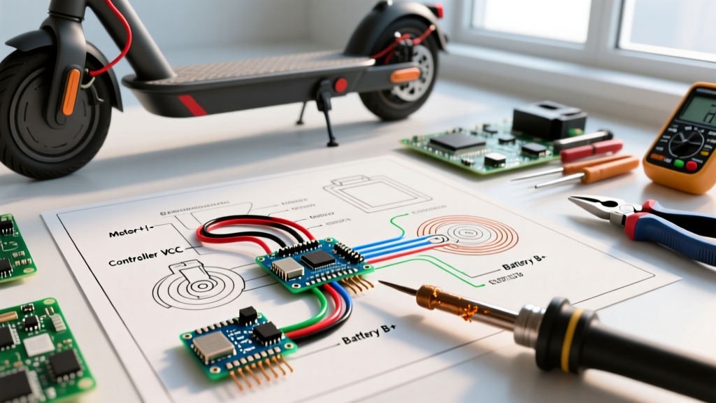
Before grabbing a multimeter, you must understand the three primary sub-circuits depicted in any standard electric scooter wiring diagram: the high-current power loop, the low-voltage logic loop, and the motor feedback loop.
1. High-Current Power Loop (Battery to Controller)
This circuit handles the raw amperage required to drive the hub motor. It typically utilizes 12 AWG to 14 AWG silicone-insulated wires terminated with XT60 or XT90 anti-spark connectors. The main power line (usually red) passes through the deck, into the main power switch, and directly into the controller's B+ terminal. The ground (black) connects to the B- terminal. A failure here usually presents as a completely dead scooter or a tripped BMS.
2. Low-Voltage Logic Loop (Ignition and Accessories)
The ignition switch does not carry main battery current. Instead, it routes a low-current 'wake' signal (typically 18 AWG to 22 AWG) from the battery's BMS to the controller's 'Lock' or 'Ignition' pin. This tells the controller's internal voltage regulator to step down the 42V/54V main supply to 5V logic for the display, throttle, and hall sensors.
3. Motor Feedback Loop (Phase and Hall Sensors)
The controller communicates with the brushless DC (BLDC) hub motor via three thick phase wires (Yellow, Green, Blue, usually 14 AWG) and a 5-pin JST-SM or Higo connector carrying the Hall effect sensors. The hall sensors require a precise 4.3V to 5.0V pull-up voltage to report rotor position back to the controller's microprocessor.
Controller Pinout Matrix: Decoding the Wire Colors
While manufacturers occasionally deviate, the industry has largely adopted a standard color code for 350W to 1000W scooter controllers. Use this matrix as a baseline when cross-referencing your specific electric scooter wiring diagram.
| Wire Color | Function | Typical Gauge | Expected Voltage / Signal |
|---|---|---|---|
| Thick Red | Main Battery Positive (B+) | 12 - 14 AWG | 36V Nominal (42V Max) / 48V Nominal (54.6V Max) |
| Thick Black | Main Battery Negative (B-) | 12 - 14 AWG | 0V (Ground Reference) |
| Thin Red | Ignition / Lock Switch Input | 20 - 22 AWG | Battery Voltage when ON, 0V when OFF |
| Thin Yellow/Red | 5V Logic Output (to Display) | 22 - 24 AWG | Steady 4.8V - 5.2V DC |
| Thin Green/White | Throttle Signal Input | 22 - 24 AWG | 0.8V (Idle) to 3.6V (Full Throttle) |
| Thin Gray | Brake Lever Cut-off Switch | 22 - 24 AWG | 5V (Disengaged) / 0V (Engaged - Active Low) |
| 5-Pin Harness | Motor Hall Sensors (VCC, GND, A, B, C) | 24 AWG | 5V VCC, 0V-5V Square Wave on A/B/C |
Diagnostic Workflows: Troubleshooting with Schematics
With the wiring diagram in hand, follow these step-by-step diagnostic flows to isolate the most common scooter failures.
Fault 1: Dead Scooter (No Power to Display)
Symptom: Pressing the power button yields no dashboard lights and no motor response.
Diagnostic Steps:
- Check the BMS Output: Disconnect the main battery harness from the controller. Set your multimeter to DC Voltage. Measure across the thick red and black wires at the battery side. If you read 0V, the BMS has tripped or gone into sleep mode. If you read full pack voltage (e.g., 41.5V on a 36V system), the battery is healthy.
- Test the Ignition Switch: Follow the thin ignition wire on your diagram. With the switch ON, measure voltage between the ignition wire and ground at the controller plug. If there is no voltage, the physical deck switch is faulty or the wire is severed inside the steering stem—a common failure point due to repeated folding.
- Verify the Controller 5V Regulator: If the battery and switch are good, measure the 5V logic output pin. If it reads 0V, the controller's internal LDO (Low Dropout) voltage regulator has failed, requiring a full controller replacement.
Fault 2: Motor Stuttering and Hall Sensor Errors
Symptom: The scooter powers on, but the motor jerks violently, refuses to spin, or the display flashes an error code (commonly Error 07 or 08 on generic displays).
Diagnostic Steps:
- Inspect Phase Wire Connections: Stuttering under load is often caused by arcing at the phase wire connectors. Inspect the bullet connectors for melted plastic or black soot. A poor connection on even one phase wire will cause the controller to misread the rotor position.
- Test Hall Sensor Pull-Up Voltage: Disconnect the motor harness. Turn the scooter on. Measure the voltage between the red (5V) and black (Ground) pins in the 5-pin connector. It must read exactly 4.8V to 5.2V. If it reads lower, the controller's 5V rail is sagging.
- Spin Test (Back-EMF): With the scooter off and the phase wires disconnected from the controller, spin the rear wheel by hand. It should spin freely. If it feels 'notchy' or heavily resisted, two phase wires are shorted together, or the motor's internal stator windings have burned out.
Fault 3: Throttle Dropout Under Load
Symptom: The scooter accelerates fine initially, but cuts out when climbing hills or applying heavy weight.
Diagnostic Steps:
- Measure Throttle Signal Sag: Back-probe the throttle signal wire at the controller while applying full throttle. The voltage should remain steady at 3.4V to 3.6V. If it drops below 2.5V under load, the throttle's internal potentiometer is failing, or the 5V supply line is suffering from voltage sag due to corroded dashboard connectors.
- Check for BMS Overcurrent Protection: If the voltage remains steady but the scooter still cuts out, monitor the main battery voltage under load. If a 36V battery instantly drops from 41V to below 32V when you apply throttle, the battery cells are degraded, and the BMS is cutting power to prevent a brownout. The issue is the battery, not the wiring.
CRITICAL SAFETY WARNING: Never bypass the main fuse or BMS cut-off to force a dead scooter to run. Lithium-ion thermal runaway is a severe risk. According to the FDNY's e-mobility safety guidelines, modified or improperly repaired battery harnesses are a leading cause of micro-mobility fires. Always use OEM-rated connectors and heat-shrink solder joints.
Multimeter Testing Protocols for 36V and 48V Systems
To accurately read an electric scooter wiring diagram, your testing equipment must be configured correctly. For a standard Fluke 117 or equivalent True-RMS multimeter, use the following settings:
- DC Voltage (V⎓): Use for testing main battery lines, 5V logic rails, and throttle signals. Ensure your meter's CAT rating is at least CAT III 600V, as inductive kickback from the motor can cause voltage spikes exceeding 100V on the DC bus when braking.
- Continuity / Diode Mode: Use strictly for testing the brake cut-off switches and the ignition switch. Never test continuity on a live circuit; doing so will blow the multimeter's internal fuse.
- AC Voltage (V~): Use this to test the three motor phase wires while the wheel is elevated and spinning. You should read a balanced AC voltage (typically 15V to 25V AC depending on RPM) across all three phase combinations (Y-G, G-B, B-Y). An imbalance indicates a blown controller MOSFET.
Upgrading and Modifying: VESC and Aftermarket Displays
Enthusiasts frequently use wiring diagrams to swap stock square-wave controllers for advanced FOC (Field Oriented Control) units like the VESC 6.x or Flipsky VX1. When performing these upgrades, the primary challenge is mapping the proprietary dashboard connectors (often 4-pin or 5-pin UART/RS485) to the standard TX/RX pins on the aftermarket controller. Always use a logic analyzer or an Arduino serial monitor to sniff the baud rate of the stock display (commonly 9600 or 19200 baud) before attempting to wire in a generic LCD.
Industry Standards and Fire Safety Compliance
When repairing or modifying wiring harnesses, adherence to safety standards is paramount. The National Highway Traffic Safety Administration (NHTSA) heavily emphasizes the importance of certified electrical systems in preventing micro-mobility fires. Furthermore, any replacement battery or BMS you wire into your scooter should comply with UL 2272 (Standard for Electrical Systems for Personal E-Mobility Devices), which mandates rigorous testing for short-circuit protection, overcharge mitigation, and wiring harness integrity under vibration.
Frequently Asked Questions (FAQ)
Can I use a generic 36V controller wiring diagram for a 48V scooter?
No. While the pinout logic (throttle, halls, ignition) remains similar, the 5V logic regulators and MOSFET voltage ratings differ. Applying 54.6V (a fully charged 48V battery) to a 36V controller's logic rail will instantly destroy the display and throttle circuitry.
Why does my scooter wiring diagram show a 'Self-Learning' wire?
Many generic controllers feature two white wires with a male/female connector. Connecting these together puts the controller into 'phase learning' mode, allowing it to automatically map the correct motor phase and hall sensor alignment. Once the motor spins smoothly in the correct direction, you must disconnect them.
What is the most common point of failure in the steering stem wiring?
The transition point where the main harness passes through the folding hinge mechanism. Repeated folding causes the 22 AWG display and brake wires to fatigue and snap internally, leading to intermittent display blackouts or brake cut-off failures. Always leave a generous service loop of wire inside the stem during reassembly.