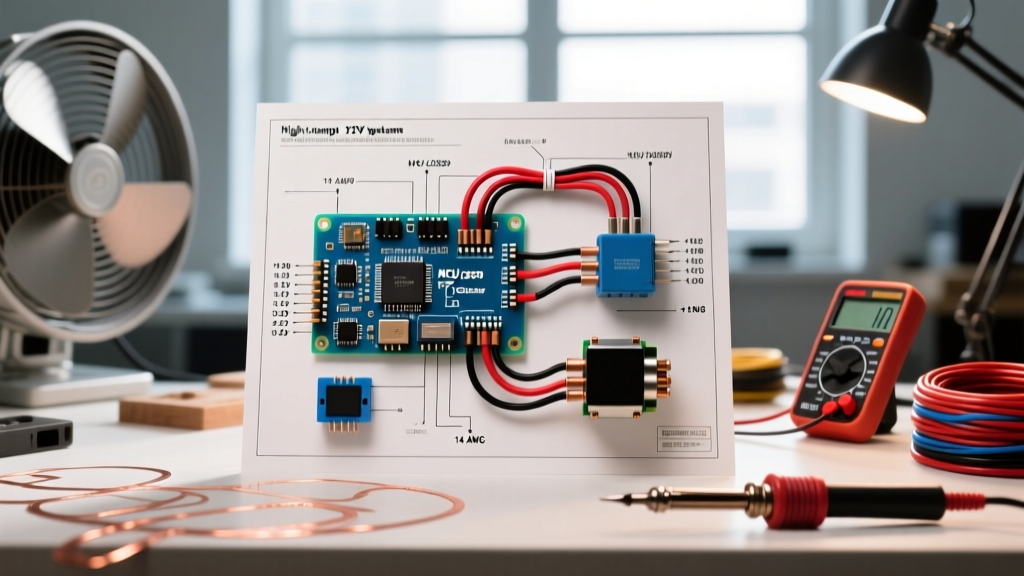

When referencing a standard wiring diagram for trailer lights 4 way setups, most DIYers focus purely on making the bulbs illuminate. However, from a safety and code compliance perspective, a functioning light is only the baseline. A poorly executed 4-way flat wiring harness is a leading cause of trailer fires, blown vehicle Body Control Modules (BCMs), and catastrophic highway collisions due to misinterpreted brake signals. In 2026, with modern vehicles utilizing highly sensitive multiplexed CANbus networks, adhering to strict electrical codes and Department of Transportation (DOT) standards is no longer optional—it is critical for vehicle warranty and road legality.
The Anatomy of a DOT-Compliant 4-Way Flat Connector
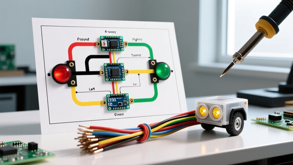
The 4-way flat connector is the universal standard for light-duty trailers (under 3,000 lbs GVWR) across North America. It handles four distinct circuits: ground, running lights, left turn/brake, and right turn/brake. While the physical connector (such as the widely used Curt 58240 or Hopkins 48115) features standard 0.110-inch to 0.125-inch blade widths, the internal wiring must strictly follow the SAE J560 color-code matrix to ensure interoperability and safety.
| Pin Position | Wire Color | Circuit Function | Max Continuous Draw (Incandescent) | Max Continuous Draw (LED) |
|---|---|---|---|---|
| 1 (Exposed/Ground) | White | Chassis Ground Return | N/A (Carries total return) | N/A (Carries total return) |
| 2 (Inner Blade) | Brown | Tail / Running / Marker Lights | 8A - 12A | 0.5A - 1.5A |
| 3 (Middle Blade) | Yellow | Left Turn Signal & Brake Light | 6A - 10A | 0.5A - 1.0A |
| 4 (Outer Blade) | Green | Right Turn Signal & Brake Light | 6A - 10A | 0.5A - 1.0A |
Code Warning: Never use the trailer hitch ball and coupler as your primary electrical ground return. While metal-on-metal contact may complete a circuit during bench testing, highway vibration, corrosion, and paint will introduce high resistance, leading to voltage drop and backfeeding across the turn signal circuits.
FMVSS 108 & Code Compliance: What the Law Requires
Trailer lighting in the United States is governed by the Federal Motor Vehicle Safety Standard (FMVSS) 108, which dictates the photometric output, placement, and wiring logic of all vehicular lamps. According to the official eCFR FMVSS 108 documentation, trailers must feature stop lamps that activate upon application of the tow vehicle's service brakes. In a 4-way setup, the brake and turn signals share the same filament (or LED cluster) on the yellow and green circuits.
Furthermore, the FMCSA Part 393 Subpart B outlines strict electrical wiring standards for commercial and heavy-duty applications, which serve as the gold standard for light-duty safety. This includes requirements for wire protection (looming or conduit), strain relief at the connector, and the prohibition of exposed copper within 2 inches of any termination point. Failing to use heat-shrink butt splices or properly sealing your 4-way plug with dielectric grease violates the spirit of these safety codes, inviting moisture ingress that causes rapid galvanic corrosion.
Wire Gauge Sizing: Preventing Voltage Drop and Fire Hazards
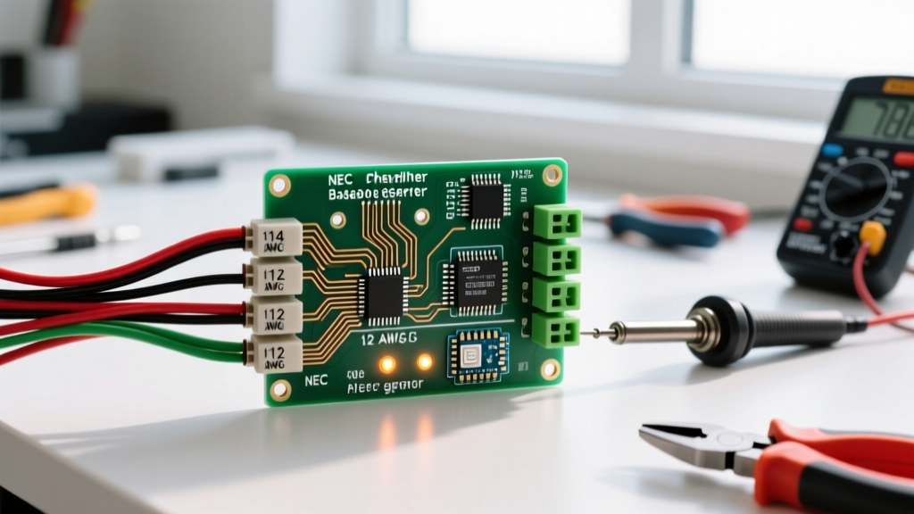
The most common safety violation in trailer wiring is undersized wire. Many off-the-shelf trailer light kits include marginal 18 AWG wire. While 18 AWG might suffice for a 10-foot utility trailer running LEDs, it becomes a severe fire hazard and performance bottleneck on a 25-foot boat trailer running incandescent bulbs. According to principles outlined in NFPA 70 (National Electrical Code) regarding voltage drop, a 12V DC system should not experience more than a 3% voltage drop (0.36V) on critical safety circuits.
| Trailer Harness Length | Lighting Type | Minimum Recommended AWG | Optimal AWG for Safety Margin |
|---|---|---|---|
| Under 15 Feet | Full LED | 18 AWG | 16 AWG |
| Under 15 Feet | Incandescent | 16 AWG | 14 AWG |
| 15 to 30 Feet | Full LED | 16 AWG | 14 AWG |
| 15 to 30 Feet | Incandescent | 14 AWG | 12 AWG |
Pro-Tip for 2026 Upgrades: If you are rewiring an older trailer, pull 12 AWG stranded, cross-linked polyethylene (XLPE) jacketed wire (often labeled as SXL or GXL automotive wire). It offers superior resistance to heat, road salt, and UV degradation compared to standard PVC-jacketed wire.
The Grounding Fallacy: Why the White Wire Isn't Enough
The white wire (Pin 1) is designed to carry the return current for all three active circuits back to the tow vehicle's battery negative terminal. In a worst-case scenario where all brake and running lights are active, the white wire carries the cumulative amperage. If your ground connection is compromised, the current will seek an alternative path, often backfeeding through the turn signal filaments, causing both left and right markers to flash in unison or dimly illuminate when the brakes are pressed.
Step-by-Step Heavy-Duty Grounding Procedure
- Locate Bare Metal: Identify a structural point on the trailer tongue, free of paint, powder coating, or rust.
- Prepare the Surface: Use a wire wheel or 80-grit sandpaper to expose bright, bare steel or aluminum.
- Use the Right Hardware: Attach a heavy-duty 12 AWG or 10 AWG ring terminal using a stainless steel bolt, a flat washer, and a star washer (internal or external tooth lock washer) to bite into the metal and prevent vibration loosening.
- Chemical Sealing: Coat the terminal and exposed metal with NO-OX-ID A-Special conductive grease. Unlike standard dielectric grease (which is an insulator), NO-OX-ID prevents oxidation while maintaining electrical conductivity.
- Secondary Frame Grounds: For trailers with pivot points (like boat trailers with surge brakes or folding tongues), run a dedicated 12 AWG ground jumper wire across the hinge to ensure uninterrupted continuity.
Edge Case Troubleshooting: Modern Vehicle Integration
As of 2026, the tow vehicle landscape has shifted dramatically. Electric vehicles (EVs) and modern trucks equipped with CANbus (Controller Area Network) systems do not use simple relay-based power delivery for trailer circuits. Instead, the Body Control Module (BCM) actively monitors the current draw on the 4-way plug to detect blown bulbs.
The LED Hyperflash and CANbus Error
If you upgrade your trailer to low-draw LED lights (e.g., Optronics STL78RB), the BCM may interpret the low amperage as a 'blown bulb' and cut power to the circuit entirely, or trigger a dashboard 'Trailer Wiring Fault' warning. The Fix: Do not splice in cheap ceramic load resistors that generate massive heat and pose a fire risk near plastic trim. Instead, install a dedicated CANbus-compatible trailer wiring converter (such as the Curt 56414 or Tekonsha 119190KIT) at the tow vehicle end, which isolates the trailer's low-draw circuit from the vehicle's sensitive multiplexed sensors.
Backfeeding via the Brake Light Circuit
If your tow vehicle has separate brake and turn signal bulbs (common in European imports and some modern American trucks), but your trailer uses a combined 4-way system, you will experience backfeeding. Pressing the brake pedal may cause the turn signals to illuminate, or vice versa. The Fix: You must install a 3-to-2 wire tail light converter (like the Tow Ready 118158) at the vehicle side. This module utilizes logic gates and block-diodes to safely merge the independent brake and turn signals into the combined yellow and green circuits required by the 4-way trailer plug, ensuring DOT-compliant signaling without frying the vehicle's BCM.
Summary Checklist for a Road-Legal Trailer
- Wire Type: GXL or SXL automotive stranded wire (14-16 AWG minimum for main runs).
- Terminations: Adhesive-lined, dual-wall heat shrink butt splices (e.g., Glarks or Knoweasy marine grade). Never use bare metal crimps or cheap vinyl insulation.
- Routing: Harness must be secured every 18 inches with UV-resistant nylon cable ties or Adel clamps, maintaining a minimum 6-inch clearance from exhaust components and moving suspension parts.
- Strain Relief: The main harness must feature a physical loop or strain-relief clamp before entering the 4-way plug housing to prevent tension from pulling the wires out of the solder/crimp joints.
- Testing: Verify continuity and amperage draw using a digital multimeter and a dedicated trailer light tester (e.g., Hopkins 48805) before taking the rig onto public roads.
Mastering the wiring diagram for trailer lights 4 way configurations goes far beyond matching colors. By respecting FMVSS 108 mandates, calculating voltage drop accurately, and engineering bulletproof ground returns, you ensure your trailer remains visible, legal, and safe under the harshest highway conditions.