
Pre-Installation Planning and NEC Compliance
Transitioning to a high-efficiency HVAC system requires meticulous electrical planning. As of 2026, the SEER2 mandates have pushed manufacturers to integrate more sophisticated compressor controls and variable-speed blowers. When interpreting the wiring diagram for a Goodman heat pump, technicians and advanced DIYers must account for both high-voltage power delivery and low-voltage control logic. Failing to properly size conductors or misinterpreting the reversing valve logic can lead to catastrophic compressor failure or voided warranties.
According to the NFPA 70 (National Electrical Code), specifically Article 440 covering Air-Conditioning and Refrigerating Equipment, the branch-circuit conductors must be sized based on the unit's Minimum Circuit Ampacity (MCA), while the overcurrent protection device (breaker) is sized based on the Maximum Overcurrent Protection (MOP) rating. These values are explicitly printed on the outdoor unit's data plate and supersede general NEC ampacity tables.
Sizing the Branch Circuit and Disconnect
For the widely installed Goodman GSZ16 series (single-stage, 16 SEER2 rated), the electrical demands scale linearly with tonnage. Below is the manufacturer-specified electrical data for planning your conduit pull and breaker selection. Note that while 14 AWG is technically permissible for the 2-ton model under NEC 310.16, most jurisdictions and best practices mandate a minimum of 12 AWG for outdoor HVAC whips to mitigate voltage drop and withstand physical stress.
| Goodman Model (GSZ16 Series) | Capacity | MCA (Amps) | MOP (Breaker Size) | Min. Copper Wire Gauge (THHN/THWN-2) |
|---|---|---|---|---|
| GSZ160241 | 2 Ton | 14.2 A | 20 A | 12 AWG |
| GSZ160361 | 3 Ton | 21.4 A | 30 A | 10 AWG |
| GSZ160481 | 4 Ton | 28.1 A | 40 A | 8 AWG |
| GSZ160601 | 5 Ton | 34.5 A | 50 A | 6 AWG |
Decoding the Wiring Diagram for a Goodman Heat Pump
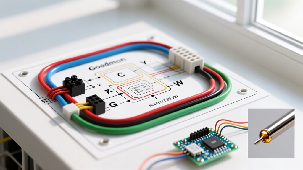
A complete installation involves two distinct electrical pathways: the 240V high-voltage power supply and the 24V low-voltage control circuit. The wiring diagram located on the inside of the outdoor unit's access panel serves as your master reference. Let us break down the physical execution of these circuits.
High Voltage (240V) Power Connections
Power is typically routed from the main service panel to a 240V fused or non-fused disconnect switch located within sight of the outdoor unit, and then to the unit via Liquid-tight Flexible Metallic Conduit (LFMC) or a pre-assembled PVC whip.
- Conductor Routing: Strip the THHN/THWN-2 insulation back exactly 3/4 inch. Goodman utilizes pressure lugs for the L1 and L2 terminals.
- Torque Specifications: Use a calibrated torque screwdriver. The standard torque requirement for Goodman residential contactor and disconnect lugs is 14 in-lbs (1.59 N-m). Under-torquing leads to arcing and melted lugs; over-torquing strips the aluminum threads.
- Grounding: A dedicated equipment grounding conductor (EGC) must be landed on the unit's green grounding screw. For a 30A circuit, a 10 AWG bare copper ground is required. Do not rely on the conduit alone for grounding.
Low Voltage (24V) Thermostat Routing
The low-voltage circuit controls the contactor coil, reversing valve, and defrost logic. Use a minimum of 18/8 unshielded thermostat wire for standard single-stage systems, or 18/10 if you are integrating advanced diagnostics or whole-home dehumidification controls. Route the low-voltage wire through a separate knockout from the high-voltage whip to prevent electromagnetic interference (EMI).
Standard Goodman terminal mapping for the outdoor unit includes:
- Y1: First-stage compressor contactor coil.
- C: 24V Common (essential for completing the control circuit).
- O: Reversing valve solenoid. Critical Note: Goodman heat pumps energize the reversing valve in cooling mode (O terminal). If your thermostat defaults to energizing in heating (B terminal, common with Rheem/Ruud systems), the system will blow cold air in the winter and hot air in the summer. Always configure the thermostat's O/B setting to 'O'.
- W1: Often routed to the indoor air handler to trigger auxiliary electric heat strips during a defrost cycle or extreme cold snaps.
Air Handler and Defrost Board Integration
Unlike gas furnaces, heat pumps require a sophisticated defrost mechanism to clear ice accumulation from the outdoor coil during winter operation. The Goodman Manufacturing Literature Portal provides detailed schematics for their Time-Temperature defrost boards, which are standard on the GSZ16 line.
Expert Insight: The defrost board monitors the outdoor coil temperature via a thermistor and tracks compressor run time. When defrost is initiated, the board reverses the valve (switching to cooling mode) and simultaneously energizes the 'W' terminal to turn on the indoor auxiliary heat strips. This prevents the home from blowing cold air while the outdoor unit melts ice. If you fail to wire the W terminal between the outdoor defrost board and the indoor air handler, the home will experience severe temperature drops during defrost cycles.
Wiring the Crankcase and Base Pan Heaters
For installations in northern climates where ambient temperatures frequently drop below 35°F (1.6°C), installing a crankcase heater and base pan heater is mandatory to prevent liquid refrigerant migration and ice damming. These accessories wire directly into the outdoor unit's terminal block. The crankcase heater connects across L1 and L2 (240V) but is usually wired on the 'line' side of the contactor so it remains energized even when the compressor is off. The base pan heater wires in parallel with the crankcase heater or to a dedicated 120V tap on the control board, depending on the specific accessory kit (e.g., Goodman BPH05).
Communicating Systems: GSZC20 Inverter Wiring
If your installation planning involves Goodman's premium communicating inverter models, such as the GSZC20 (20 SEER2 variable-speed), the wiring diagram changes drastically. These units do not use standard 24V Y and W signals. Instead, they utilize a proprietary 4-wire communicating data bus.
The communicating terminal block requires:
- R: 24V Hot
- C: 24V Common
- I (or D): Data/Communication line
Because the outdoor unit, indoor air handler, and communicating thermostat (like the Goodman ComfortNet CTK04) 'handshake' via serial data, standard thermostat wire is insufficient for long runs. Goodman requires the use of 18 AWG shielded twisted-pair cable for the data lines to prevent signal degradation. The shield must be grounded at one end only (typically at the air handler) to prevent ground loops that can fry the inverter control board. As of 2026, replacing a communicating control board costs upwards of $850 in parts alone, making proper shielded wiring a non-negotiable financial safeguard.
Common Edge Cases and Installation Failures
Even with the correct wiring diagram for a Goodman heat pump in hand, field conditions introduce variables that can cause system faults. Review this troubleshooting matrix before energizing the system:
| Symptom / Fault Code | Probable Wiring Error | Corrective Action |
|---|---|---|
| Compressor hums but won't start; breaker trips instantly. | L1 and L2 landed on same phase, or severe voltage drop. | Verify 240V across L1/L2 at the contactor. Check for undersized wire on runs over 75 feet. |
| System cools in winter, heats in summer. | Reversing valve wired to 'B' instead of 'O' at thermostat. | Access thermostat installer setup menu; change O/B configuration to 'O' (Cooling). |
| Indoor blower runs, outdoor unit does not engage. | Y1 signal wire broken or not landed on terminal block. | Use a multimeter to check for 24V between Y1 and C at the outdoor terminal block when cooling is called. |
| Frequent short-cycling; defrost board LED flashes 3 times. | Defrost thermistor unplugged or shorted. | Verify the 2-pin thermistor connector is fully seated on the defrost board and clipped to the outdoor coil return bend. |
Final Verification Protocol
Before closing the access panels and applying high voltage, perform a point-to-point continuity test on all low-voltage connections. The U.S. Department of Energy emphasizes that proper commissioning, including verifying electrical connections and refrigerant subcooling, is critical to achieving the rated SEER2 efficiency. Once continuity is confirmed, apply 240V power, wait 60 seconds for the control board to initialize, and initiate a test cycle at the thermostat. Measure the amp draw on L1 and L2 using a clamp meter; it should closely match the Rated Load Amps (RLA) on the compressor data plate under standard summer conditions.