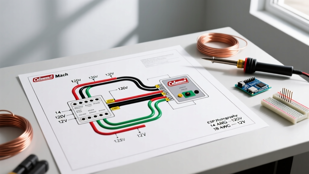

The Dual-Voltage Reality of RV and Mobile HVAC Systems
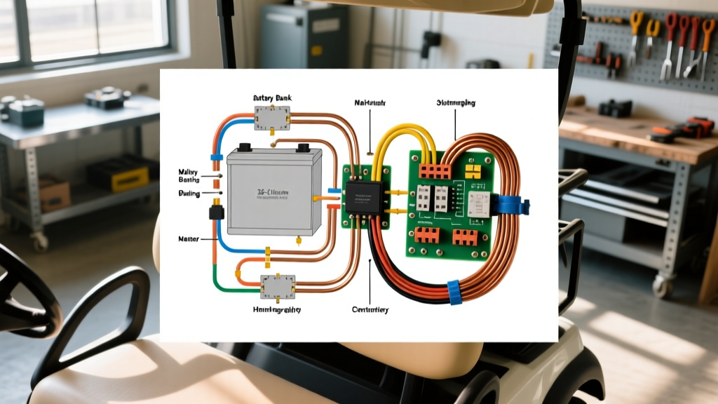
When researching a wiring diagram for Coleman Mach thermostat configurations, most DIYers and technicians focus exclusively on the low-voltage control wires behind the wall plate. However, from a comprehensive Panel and Breaker Guide perspective, the thermostat is only the brain of the operation. The true electrical heavy lifting happens at the distribution panel, where high-voltage alternating current (AC) meets the inductive loads of the rooftop compressor. Whether you are wiring a Coleman Mach 3 Plus (13,500 BTU), a Mach 15 (15,000 BTU), or integrating the popular 9330 and 9530 digital wall thermostats, understanding the dual-voltage architecture is critical for safety and system longevity.
Unlike standard residential HVAC systems that often use a 24V AC transformer for thermostat control, RV and mobile home Coleman Mach systems typically rely on a 12V DC control circuit to trigger relays, while the compressor, blower motor, and optional heat strips draw directly from a 120V AC main panel. This split architecture means you must master two entirely different electrical domains: the 18 AWG low-voltage thermostat routing and the 12 AWG or 10 AWG high-voltage breaker sizing.
Decoding the Wiring Diagram for Coleman Mach Thermostat (9330/9530 Series)
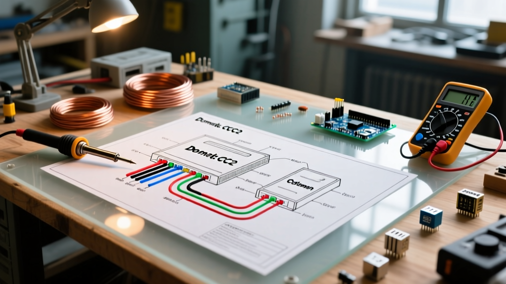
The Coleman 9330 and 9530 series digital thermostats are the industry standard for controlling Mach 1, Mach 3, and Mach 15 rooftop units. The low-voltage wiring harness usually consists of a multi-pin connector or a color-coded wire bundle that runs from the thermostat directly to the rooftop unit's control board or relay box. Correctly identifying these wires is the first step in your wiring diagram for Coleman Mach thermostat installation.
Low-Voltage Control Pinout and Wire Functions
| Wire Color | Function / Designation | Voltage / Signal Type | Panel / System Notes |
|---|---|---|---|
| Red | 12V DC Power (+) | 12V DC Constant | Fused at the 12V DC fuse panel (typically 3A or 5A). |
| White | 12V DC Ground (-) | 12V DC Return | Must terminate at the main 12V DC negative bus bar. |
| Yellow | Cooling Compressor | 12V DC Switched | Triggers the 120V AC compressor contactor on the roof. |
| Green | High Fan Speed | 12V DC Switched | Engages the high-speed winding of the 120V blower motor. |
| Blue | Low Fan Speed | 12V DC Switched | Engages the low-speed winding of the 120V blower motor. |
| Orange | Heat Strip / Furnace | 12V DC Switched | Activates the 120V AC heat strip relay or 12V furnace fan. |
Note: Always verify your specific unit's schematic, as aftermarket upgrades or older analog Coleman models may utilize slightly different color codes. Always use a multimeter to verify the Red wire carries a steady 12V to 13.6V DC before connecting the thermostat baseplate.
Panel and Breaker Sizing: The High-Voltage Side
The most common failure point in RV and mobile home HVAC setups is not the thermostat itself, but an undersized breaker or incorrect wire gauge feeding the rooftop unit. The National Fire Protection Association (NFPA) outlines strict guidelines in the National Electrical Code (NEC) regarding overcurrent protection for motor-driven appliances. Because AC compressors have high Locked Rotor Amps (LRA) during startup, the breaker must handle the inductive spike without nuisance tripping, while still protecting the wire from thermal overload.
As of 2026, with fluctuations in copper pricing, some DIYers attempt to save money by using 14 AWG wire on 15A breakers for smaller AC units. However, the RV Industry Association (RVIA) and NEC Article 210.23 strongly advise against this for inductive HVAC loads. A 13,500 BTU Coleman Mach 3 may only draw 11 to 13 Running Load Amps (RLA), but a voltage drop over a long wire run from the panel to the roof can cause the compressor to pull excess amperage, melting 14 AWG insulation before a 15A breaker trips.
Breaker Sizing and Wire Gauge Matrix
| Coleman Mach Model | Capacity / Accessories | Max Overcurrent Protection (Breaker) | Minimum Copper Wire Gauge |
|---|---|---|---|
| Mach 3 Plus | 13,500 BTU (Cool Only) | 20 Amp (Standard Thermal-Magnetic) | 12 AWG Stranded (RV rated) |
| Mach 15 | 15,000 BTU (Cool Only) | 20 Amp or 30 Amp (Check LRA data plate) | 12 AWG (20A) or 10 AWG (30A) |
| Mach 3 / 15 | AC + 3kW Heat Strip | 30 Amp (HACR Rated Breaker) | 10 AWG Stranded Copper |
| Mach 15 | AC + Dual 3kW Heat Strips | 50 Amp (Requires heavy-duty panel bus) | 8 AWG or 6 AWG Stranded Copper |
Step-by-Step Panel to Thermostat Routing Best Practices
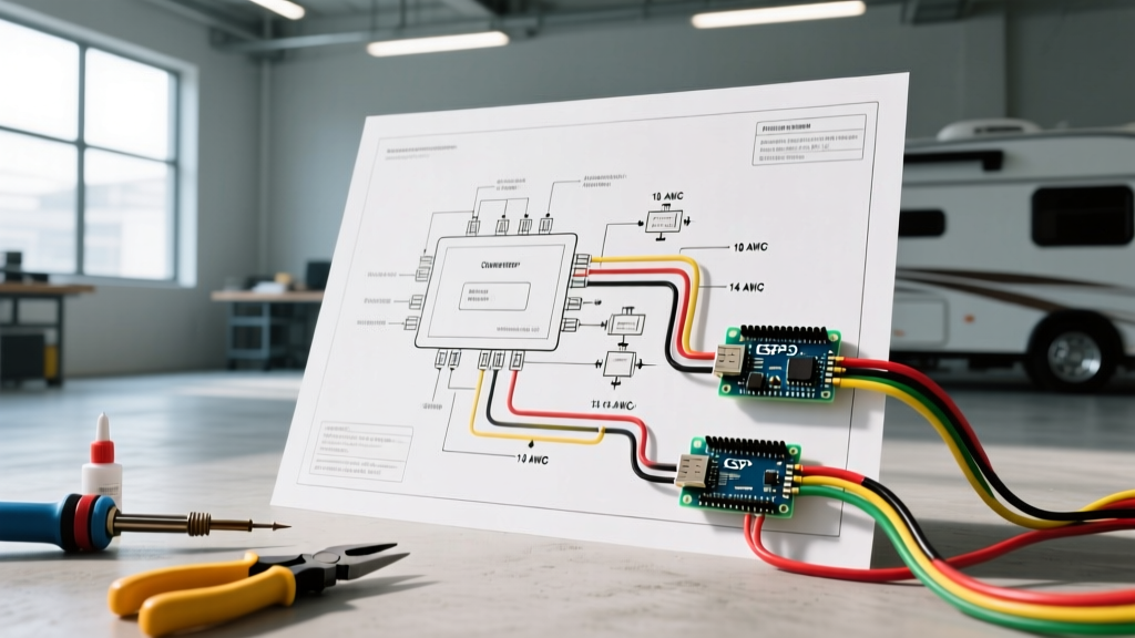
Proper routing ensures that the high-voltage electromagnetic field does not interfere with the low-voltage thermostat signals, which can cause the Coleman digital display to flicker, reset, or throw ghost error codes.
- Separate the Conduits: Never run the 18 AWG thermostat control wires in the same conduit, loom, or tight bundle as the 120V AC power wires. Maintain a minimum physical separation of 2 inches wherever the wires must cross paths.
- Use HACR Rated Breakers: When installing the breaker in your main distribution panel, ensure it is marked HACR (Heating, Air Conditioning, and Refrigeration). These breakers are specifically designed to handle the magnetic inrush currents of compressor motors without tripping prematurely.
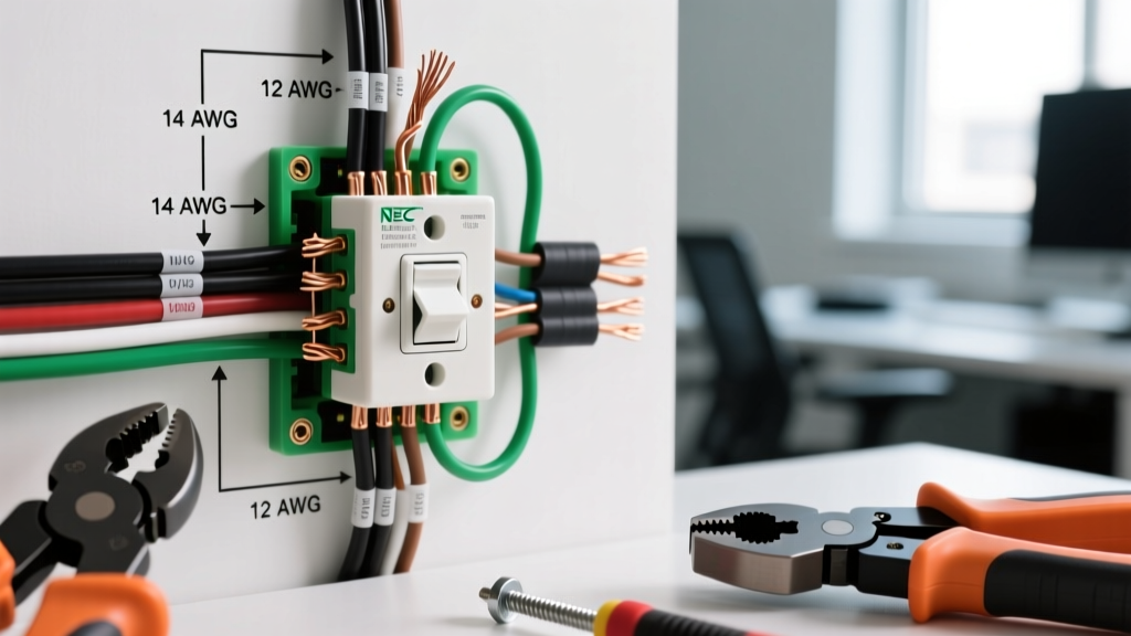
- Terminating Stranded Wire: RV and mobile home panels often use residential-style breakers designed for solid copper wire. When terminating 10 AWG or 12 AWG stranded wire into a breaker lug, use crimp-on wire ferrules or pin terminals. Wrapping bare stranded wire around a screw terminal can lead to 'birdcaging' (where individual strands splay out), causing high-resistance hot spots and potential panel fires.
- Torque Specifications: Use a calibrated inch-pound torque screwdriver to tighten the breaker lugs. As of recent NEC updates, torqueing to the manufacturer's specified value (usually 40-50 in-lbs for standard 20A/30A breakers) is a mandatory code requirement to prevent thermal expansion loosening over time.
Advanced Troubleshooting: When the Diagram Meets Reality
Even with a perfect wiring diagram for Coleman Mach thermostat setups, edge cases occur. Understanding how the panel breaker interacts with the thermostat relays is key to rapid diagnostics.
Troubleshooting Matrix for Panel and Thermostat Conflicts
| Symptom | Probable Electrical Cause | Diagnostic Action & Solution |
|---|---|---|
| Thermostat display is completely dead. | Blown 12V DC fuse at the main RV fuse panel, or severed Red/White wire. | Check the 12V DC fuse panel for a blown 3A/5A automotive blade fuse. Test continuity on the Red wire. |
| Thermostat clicks, but compressor does not start; breaker trips instantly. | Dead short in the 120V AC rooftop wiring, or a seized compressor pulling infinite LRA. | Disconnect the 120V AC load at the roof junction box. Reset breaker. If it holds, the fault is on the roof (capacitor or compressor). |
| Thermostat clicks, compressor hums, then breaker trips after 5 seconds. | Voltage drop due to undersized wire (e.g., 14 AWG used instead of 12 AWG) or failing start capacitor. | Measure voltage at the roof unit while the compressor attempts to start. If voltage drops below 105V, upgrade wire gauge or install a hard-start kit. |
| Heat strip works, but AC fan runs on high only. | Blue wire (Low Fan) disconnected at thermostat base or shorted to ground in the wall cavity. | Verify 12V DC signal on the Blue wire at the roof control board when thermostat is set to Low Cool. |
Safety, Grounding, and Code Compliance
Electrical safety in mobile environments is unforgiving. The vibration of travel can loosen panel connections, and the presence of moisture on the roof can create ground fault pathways. The Occupational Safety and Health Administration (OSHA) and NFPA emphasize the critical nature of proper grounding in all electrical installations.
Expert Warning: Never use the 120V AC ground wire as a substitute for the 12V DC ground return path for your Coleman thermostat. While both systems ultimately tie back to the chassis or main grounding rod, mixing AC and DC grounding circuits can introduce 120V AC ripple into your 12V DC system during a fault condition, instantly destroying the thermostat's microprocessor and posing a severe shock hazard.
By treating the wiring diagram for your Coleman Mach thermostat not just as a low-voltage puzzle, but as an integrated component of your overall panel and breaker infrastructure, you ensure a climate-controlled environment that is both comfortable and fundamentally safe. Always verify your specific unit's data plate for exact RLA and LRA values before finalizing your breaker and wire gauge selections.